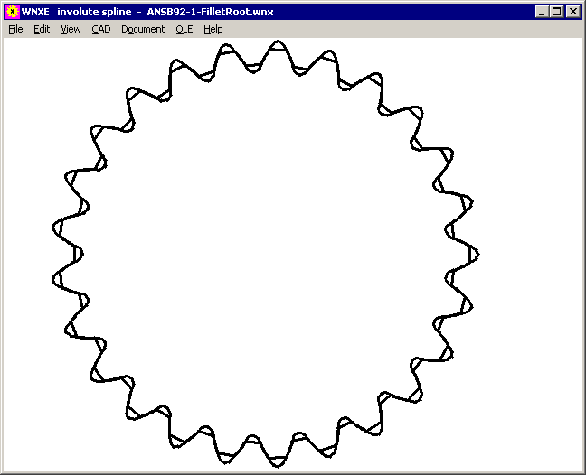
WNXE - New Software for Involute Splined Joints

WNXE is a flexible tool for calculation of any involute spline. Internal and external involute splines can be designed in short time, with output of true-scale profile drawing, or designing the counterpart internal/external spline. Input options are various: module or pitch, tooth heights or tooth height coefficients or major and minor diameter, in millimeters or inches, profile shift coefficient, addendum modification or tooth thickness or gap width or dimensions over/between pins or span measurement. And the counterpart spline optionally can be calculated from flank clearance and backlash. WNXE is available now, price is 375 Euro for individual license.
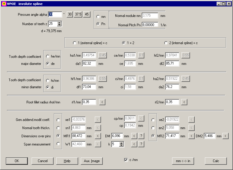
ZAR5 – Pre-Dimension for Multistage Planet Gears

Pre-Dimension of multistage planet gears to achieve a large transmission ratio, is a new option in ZAR5. With only few input data you can estimate size of the sequential planet gear stages. Hence input of material data is equal for every gear and every stage. And every stage is a planetary gear with input sun, output carrier which drives next sun gear, and blocked ring gear. By means of a factor you can define dividing of transmission ratios: If "in-1/in"=1, equal transmission ratio for each stage. For "in-1/in"=1.25, transmission ratio of the next stage is 25% higher than former stage.
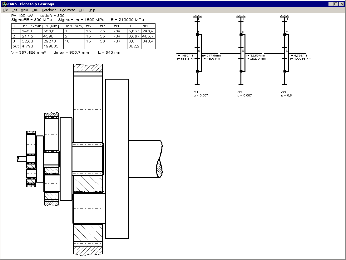
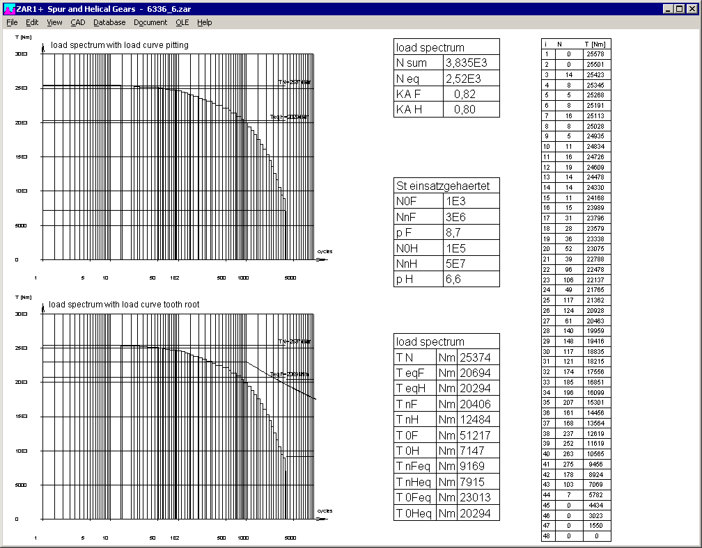
ZAR1+, ZAR2, ZAR5, ZAR6: Load Spectrum: Input Table with copy and paste

Load spectrum can be entered step by step, as used, or new as table with possibilty of copy and paste or import/export with other programs via Windows clipboard. In the table menu, you can configure if x coordinate in diagram (load cycles) should be linear or logarithmic scale. And at "View->Error" you can check load spectrum input for errors.
ZAR1+ Meshing Interference
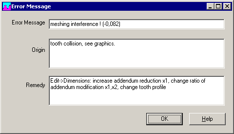
If meshing interference in tooth contacts, you get an error message. This error message was enhanced by the overlap in mm as help parameter when optimizing the gear.

ZAR1+ Warning: z0 cutter !
For calculation of ring gears, number of teeth z0 and profile shift x0 of the pinion cutter is needed for calculation of tooth form coefficients YF and YS according to ISO 6336. Because the input button "pinion cutter" at Edit -> Cutting Tool" can easily be lost of sight, you get now a warning "z0 cutter !" if cutter pinion number of teeth is wrong or not defined.
FED1+ Coil distance aW and Tolerances e1,e2 in Quick1,3,4
Coil distance aW (0,1,2,n,c) has been added to the table with deflections, forces, and stresses in Quick3 and Quick4 View.
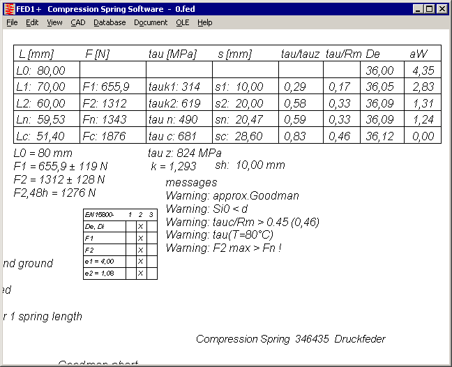
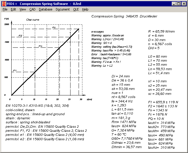
Tolerances for parallelism and angle e1 and e2 have been added in Quick1 View (in brackets). In tables with tolerance grades in Quick3 and Quick4, tolerances e1 and e2 are also printed now. However, tolerance grades and tolerances e1 and e2 are no longer displayed if end coils are lined-up, but not ground. And for hot-coiled springs and self-defined tolerances, a table with tolerances and tolerance grades is drawn now.
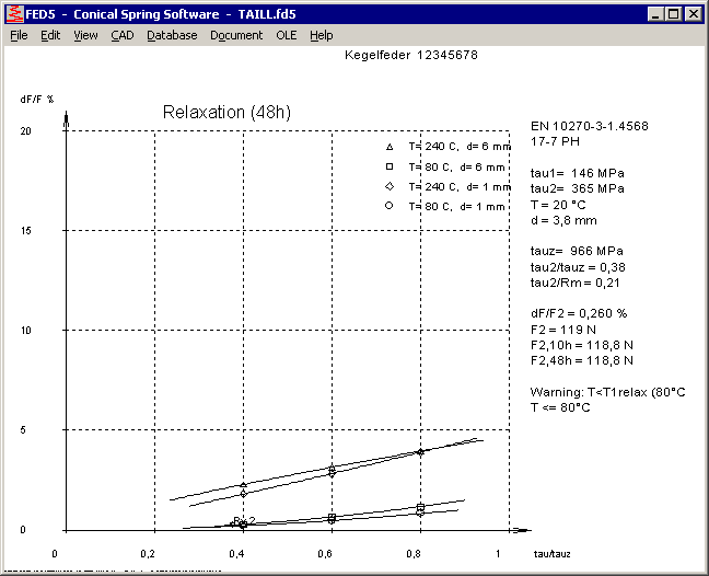
FED1+, 2+, 5, 6, 7: Relaxation as function of tau/tauz
Relaxation curves with the coefficient tau/tauz (instead of tau) has been added into all compression spring programs now. Tauz is the permissible shear stress as function of wire diameter. I compared the curves of all materials to check if relaxation as function of wire diameter is similar than permissible shear stress as function of wire diameter. In this case the curves for different wire diameter would be equal. Unfortunately, most material curves differ. Only the curves for VDC and TDC according to EN 10270-2 and 1.4568 according to EN 10270-3 are nearly identical for wire diameters d=1 mm and d=6mm.
Database Spring Materials – ISO 8458 and EN 10270
Material values according to ISO 8458-2 and EN 10270-1 are equal, and material types are equal: SL, SM, DM, SH, DH. (S for static, D for dynamic, L for low, M for middle, H für high). In the spring material database, ISO 8452-2 names has been added in NAME3 of EN 10270-1 materials. Old names (DIN 17223-1) were moved or deleted.

FED3+ V17.5
In FED3+ V17.5 and V17.5.1 at "Edit->Material", input data (shot-blasting, coiling direction) were not used in every case. Click first "Calc" button and then "OK" to accept the data. Or you can request a free update from release V 17.5 to V17.5.2.
FED1+, FED5, FED6: Mandrel and Bore diameter with 2 digits
If the diameter of mandrel or bore is less than 16 mm, it is printed in mm with 2 (instead of 1) decimals now in the production drawing.
SR1 – Material Data
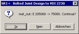
When opening an old SR1 file, program detects if material data Rm, Re, pG or E module differ with the actual material database and show an error message. This indicates that material data in the database has been modified. Compare calculation with printout of old calculation to see the difference. To remove warnings, just resave the file.
SR1 – Compare Material Data and Database Data
Since release 20.2, a warning "old value <> new value" appeared if material database data differed between stored values and new database values when opening an old SR1 file. Because of updating many old material names with new material names, since Version 20.6 idle messages like " St 50 <> E295" are not reported any more. Warnings are reported only if material data have been changed in the database and this may influence calculation results.
SR1 – Consider Bolt Length Tolerance
Bolt length tolerance for hexagon head bolts according to ISO 4014 and ISO 4017 is "IT 15" for allowance class A and "IT 17" for allowance class B. Bolts larger than M30 and longer than 160 mm get class B tolerances. For hexagon socket head bolts to ISO 4762 is no selection, tolerances are equal with allowance class A. And the same for hex flange bolts to EN 1662 and EN 1665.

Length tolerances and elongation of the bolt and deflection of the clamping plates are considered now when checking available thread depth. A new error message "LK+tG < Lmax" shows that in worst tolerance case bolt collides with end of thread in TTJ joint. If you get additionally the old message "thread depth !", this is even the case with nominal dimensions without tolerances.
Should bolt length tolerance also be considered for thread strip safety calculation? Or is it already considered in the addition mzu?
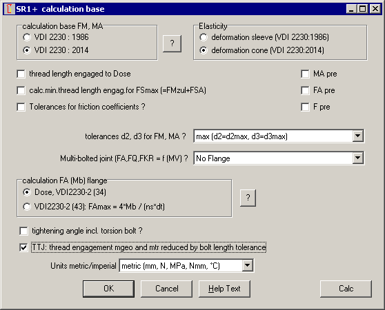
The user can decide himself if he wants to consider bolt length tolerance for calculation of engaged thread length "mtr" or not at "Edit->Calculation Method".
SR1 – E Module of Nut for Calculation of deltaM
According to VDI 2230-1:2014, elastic resilience deltaM of the nut thread is calculated with the E module of the nut thread if TTJ (tapped blind hole joint), but with the E module of the bolt if TBJ (through bolted joint with nut). But why??
SR1 calculates according to VDI 2230, however in earlier versions the E module of the nut material had been replaced by standard E module of 205000 Mpa when switching between TTJ and TBJ joints.
GEO1+, GEO2: Coordinate Input Table
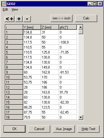
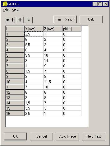
Coordinates and angles of the cross-section or rotation area can be entered in a new table now. With copy and paste you can move cells or import/export data from/to MS Excel or other programs. Cells are marked by cursor keys together with shift key.
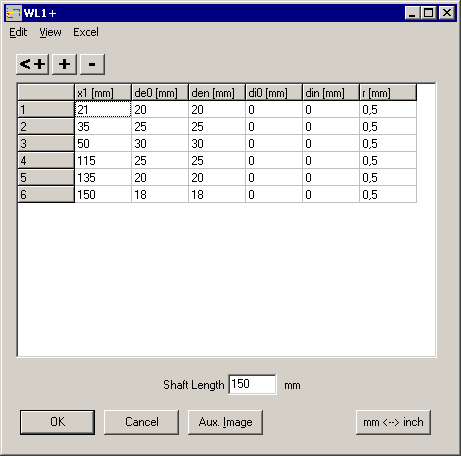
WL1+: Copy and Paste via Clipboard
Input of dimensions, radial and axial forces, path loads, bending moments and torque gets copy and paste functions to move or import/export data via Windows clipboard.
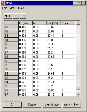
FED6, FED7, FED10, ZAR4, GEO4: Tables with copy and paste
Tables for input of coil sections or load-deflection diagrams in FED6 and FED7, input of spring geometry in FED10, and input tables for pitch curve or cam geometry in ZAR4 and GEO4 got a menu with copy and paste and import/export functions.
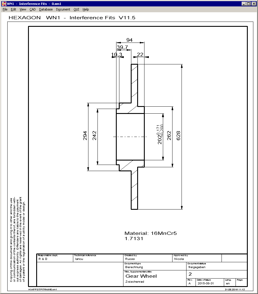
WN1 – Production Drawing
New in WN1 is hub drawing with dimensions as production drawing. Drawing header is configurable, and drawing data, names and modifications can be entered in WN1.
FED1+ Dimensioning or Recalculation after Modification of Temperature
If you change operating temperature at "Edit->Application", you have to select "Dimensioning or Recalculation?". If dimensioning, number of coils will be modified. Else spring loads are recalculated.
All Programs: Drawing Header Configurable, Default Setting ISO 7200
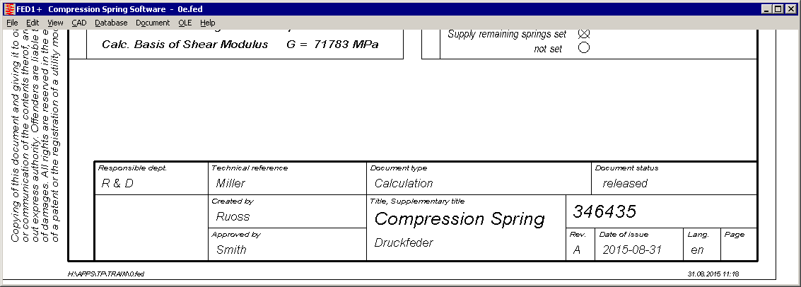
The drawing header of all production drawings and table drawings is configurable now (at "File->Settings->Drawing). Default Setting is "ISO 7200 Fig.2".
In spring drawings, cell 13 or cell 12 (additional indications) was removed. But text, if any, is printed, without cell and 6 mm higher than before.
ISO 7200 header and DIN 6771 header differ. Self-defined changes in drawing and calculation are not documented in ISO 7220 header, only the index letter. And only the issue date is listed. However, ISO 7200 header includes additional fields "Responsible dept.", "Document type", "Document status". At "Document->Drawing data" you can input these texts, if an ISO 7200 drawing header was defined at "File->Settings->Drawing". Other data are used commonly for DIN and ISO drawing header:
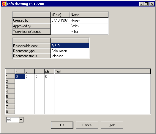
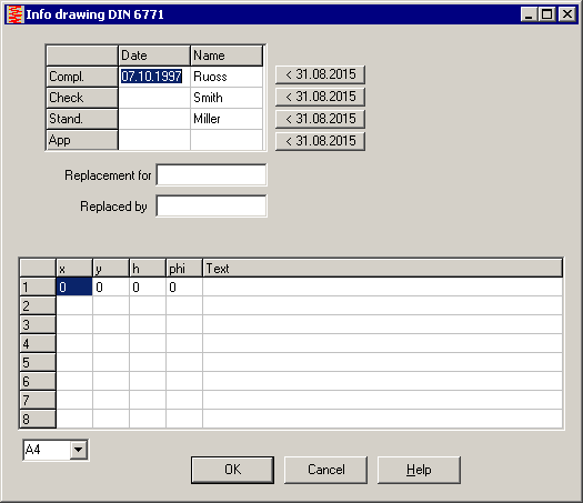
Technical reference: stand.
Created by:          compl.
Approved by:         check.
Changes:             modification index +1
POLYLINE usable for logo drawing
Polylines are now allowed to be used in logo drawings and the modified dxf file for inserting your company logo in the drawing header. Use our free tool DXF2LOGO.EXE to convert your DXF drawing into the required $LOGO_1.DX$ file, then copy into temporary directory and set R/O file attribute.
One Logo drawing for all drawing headers

Dependent on the configured drawing header, your logo drawing will be scaled and positioned to fit.
In ISO 7200 Fig.1, the "legal owner" field is only 30x16mm, but in ISO 7200 Fig.2 it is more than double size (70x26mm). If you do not create your own $LOGO_1.DX$ drawing, your company name from the license text is printed in the "legal owner" cell.

Drawing header with or without copyright note

At "File->Settings->Drawing" you can configure if a copyright note should be printed on the left border or not.
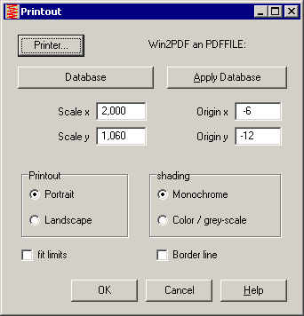
Print A4 Production drawing without Border to Printer
To print production drawing without border on printer, it must be lightly enlarged and moved. Settings can be saved in the printout database: Scale x/y: 2,0/1,06. Origin x/y: -6 / -12.
Configure Windows Size

After Installation or "<" button, window size is set maximum. On wide screen display, drawings may appear stretched and circles appear as ellipses. Two new "<" buttons set the relation of horizontal to vertical pixels 4:3 to avoid this effect.
Update History online
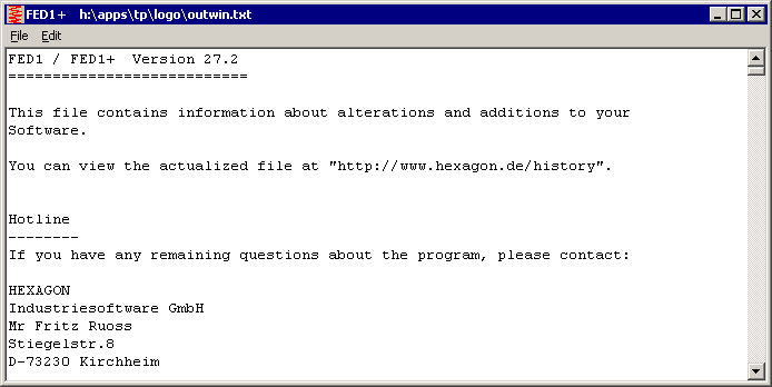
At "Help -> History" you can show description of updates until your present release. To get update information about later updates from the web, a new menu item "Help -> History (www)" is available now with an internet link to the updated update history of your program. Login data are required for access to this page, see info email.

"Document Links" instead of "Document Setup" and "Document 1..5"
The functions for linking any external documents has been integrated in one dialog box.

At "File 1" .. "File 5" you define the documents to be linked. With "Exec File" you show or run the linked document. If document file is not linked with an application under Windows, you have to input the appropriate program and run with "Exec Prog". Else, you can use "program" input for description or remarks.
Tip: Compare Calculation Results
Use Shift-F2 keys to switch between latest 2 calculations, or Shift-F3 or Shift-F4 to compare 3 or 4 results. Result graphic can be configured at File->Settings->Settings: Result Screen.
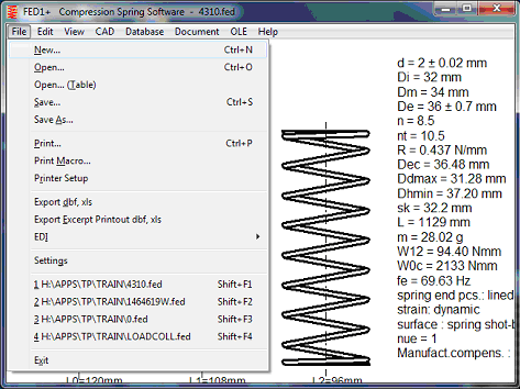
To compare more than 4 calculations, copy the files in a subfolder, then "File->Open Table"