SR1 – Fatigue Strength for Finite Life
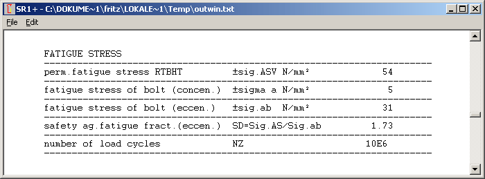
New in SR1 is calculation of load cycles from fatigue loading.
Dynamic safety SD is calculated from stress amplitude Sigma a or Sigma ab, and permissible stress amplitude for endurance limit Sigma ASV or Sigma ASG. Endurance limit refers here to ND = 2*10^6 load cycles. In VDI 2230:2003 is described how stress amplitude can be if only few (some thousand) load cycles apply:
RTBHT: Sigma AZSV = Sigma ASV (ND / NZ) ^ 1/3
RTAHT: Sigma AZSG = Sigma ASG (ND / NZ) ^ 1/6
If we set calculated stress amplitude Sigma a as Sigma AZS(V,G), we can calculate number of load cycles with safety SD = Sigma ASV / Sigma AZSV or. Sigma ASG / Sigma AZSG:
RTBHT: NZ = ND * SD^3
RTAHT: NZ = ND * SD^6
Safety SD = 1.0 refers to NZ = 2 million load cycles according to VDI 2230 definition. SR1 calculates (theoretical) load cycles also for safety > 1.

SR1+ Flange Drawing
Drawing of flange is shown after input of flange data now. Drawing had to be corrected: pitch circle diameter and outside diameter was drawn double size in earlier versions.
WL1+ Diagram Bending Stress
At "Diagram Bending Stress", resulting line x-yz was not displayed in earlier versions.
ZAR3 – Lubricant
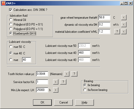
New Lubricant "Klübersynth GH 6" has been added. For some applications you can achieve better efficiency and higher lifetime when using this lubricant.
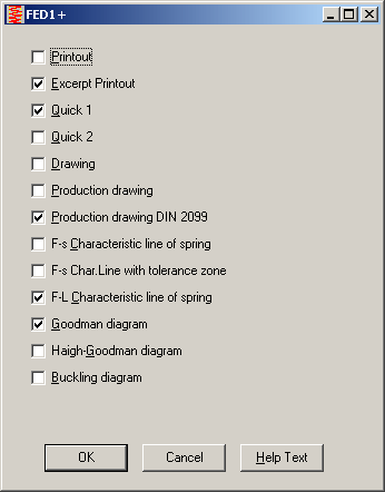
FED1,2,3,4,5,6,7,8,9: Print Macro
Here you can check what results, drawings and diagrams should be printed sequentially. Default settings can be saved at "File->Settings->Save".
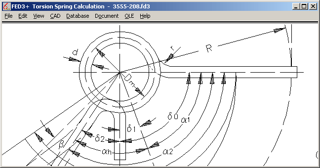
FED3 – Stress coefficient q
Stress coefficient q is calculated for tangential legs from coil ratio Dm/d, but for bended legs from the "coil ratio" of the bending 2*r/d (highest stressed area).
For tangential legs, q has to be applied on dynamic applications and for load against coiling direction (opening spring).
For bended springs the same, but the q factor even has to be applied for static applications in coiling direction, because the bending direction is against coiling direction in this case (tension at inner radius). This case is not explained in EN 13906-3.
Printing of True-Scale Drawings by means of DXFPLOT
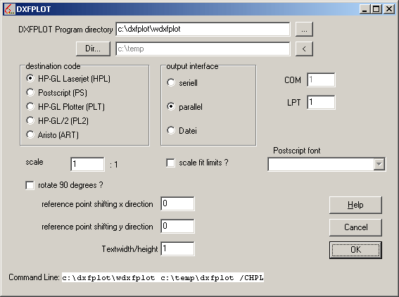
Drawings printed at "File->Print" are not true to scale. To print true-scale drawings, you have to use CAD software, or you can use our DXFPLOT software (123 EUR), if your printer can handle HP/GL (PCL5, PCL6). DXFPLOT is used as external program in command line mode. True-scale drawings are printed at CAD menu, then select "DXFPLOT – send to printer/plotter". User interface was improved now, so that you only have to define scale in normal case For direct printing, take note of redirecting LPT interface to printer.
Printout
Time was added to printout. Date and time are now printed in header line 2, so there is more space for file path in line 3.

Production Drawing

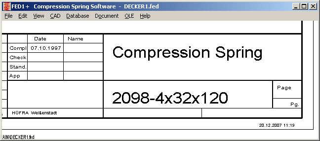
Program name and version will be printed now on top of production drawings, Date and time are printed on right bottom of the drawing.
