

For planet gears, the assembly rule has to be considered:
(zH+zS) / qp must be integer value !
(zH and zS = number of teeth hollow gear and sun gear, qp = number of planets).
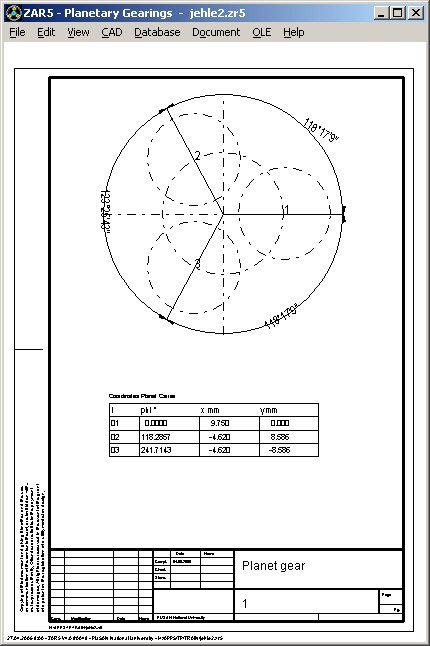
Angle for alignment of planets on planet carrier is 360° / qp. If your planet gear design does not fulfil the assembly rule and you have no possibility to modify ring gear or sun gear, or if the number of planets should be changed on existing gear, planets may be assembled by means of asymmetric planet positions on the planet carrier. The new release 4.0 of ZAR5 calculates planet angles and planet coordinates on the planet carrier, according to following formula:
Planet angle phi(i) = round [i / qp * (zH + zS)] * 360° / (zH + zS)
with i = 0 .. qp-1
round() : round to nearest integer value
Error message "Error: Assembly !" has been replaced by "Warning: unsymmetric !" .
New production drawing "planet carrier" contains angles and coordinates for planet bores on the carrier.
ZAR3 - Pre-Dimensioning
A new, more convenient input window was created for pre-dimension of worm gears by input of transmission ratio and power data. You can also enter output power data now (P2 = P1*efficiency).

ZAR3 – alphan, alphax = f (profile type)
The most commonly used profile shapes for worm gear are ZI, ZA, ZN and ZK type. For ZA worm, generation angle lays in axial profile (alpha 0 = alpha x). For ZI-, ZN and ZK worm, generation angle plain lays in angle gamma_m to worm axis (alpha 0 = alpha n). In earlier versions, ZAR3 used alpha x = alpha 0 for all profiles. Now, ZAR3 calculates alpha_n and alpha_x due to selected worm type. Generation angle alpha_0, axial pressure angle alpha_x and normal pressure angle alpha_n are listed in printout and gear tables.
Maximum outside diameter de2 of the worm wheel is by default calculated from outer diameter at throat da2 and module (de2 = da2+mt2). Now, you also can modify de2 (at Edit->Production).
Additional material data are required for strength calculation according to DIN 3996 (tauFlimT, YNL, YW). A new input window has been created for more convenient input of these values.

ZAR3 - Export ZAR1
ZI worm and worm wheel (at throat) can be displayed in ZAR1+ . In radial profile, worm is a gear rack, and worm wheel a helical gear (beta = gamma m).

If you want to see axial profile of ZI worm, enter number of teeth z1 in ZAR1+ (for z1>1 only). Helix angle beta = 90° - gamma_m for this case.

Helix angle gamma_m of worm has been added to the input window "Dimensions" in ZAR3.
Input of gamma_m recalculates dm1, dm1/a and module m.
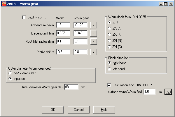
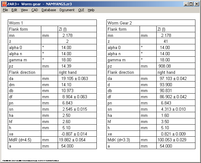
An extended version ZAR3+ for worm gears will be available soon. Additional features are: free definable tooth height factors and profile shift coefficients, input of gear quality and tolerances for tooth thickness and center distance, calculation of dimension over pins for worm and dimension over balls for worm gear, tooth profile drawings of worm and worm gear with CAD export.
ZAR1+ Input Window for Calculation according to DIN 3990 part 1-3 (ISO 6336)

Input for pinion bearing and tooth profile corrections have been integrated into one window now. This is more clear and accelerates input and modifications. A mouse click into "?" buttons displays auxiliary images.

ZAR1+ Gear Rack Center Distance
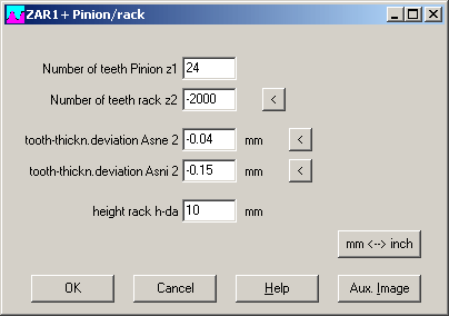
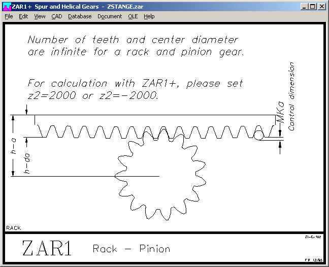
At "Edit->Special Dimensions->Rack-Pinion", you may now enter height of gear rack (from back of rack until tooth external line). ZAR1+ calculates distance from back of rack until center of pinion (h-a = a - da2 / 2 + h-da).
       ----------------------------------------------------------------------
       Center distance                   a        mm          -2469.000
       ----------------------------------------------------------------------
       Center distance - Gen.pitch diam.2a-r2/2   mm            31.000
       ----------------------------------------------------------------------
       height rack                       h-da     mm            10.000
       ----------------------------------------------------------------------
       rack Center distance              h-a      mm            38.806
       ----------------------------------------------------------------------
ZAR1+ Kv, KFalpha, KHalpha, KFß, KHß
The running-in value yp (yf, yalpha) was calculated according to DIN 3990 part 1 method C until now, however all other factors for calculation of dynamic coefficient Kv according to (more precise) method B. For calculation according to DIN 3390 part 41, the running-in value was calculated according to method B, however under condition (according to DIN 3990 part 41) that gears are case-hardened or nitrided. Running-in value is also used for calculation of load distribution factors KFalpha, KHalpha, KFß, KHß according to method C2.
Calculation of running-in value is now (from release 16.0) completely calculated according to method B. For reasonably calculated gears, there may rarely be seen any difference between earlier and newer version. Significant differences result in calculation of fast-running gears of low load (Warning Ft/b*KA < 100).
ZAR1+ and ZAR5 use the same calculation kernel, the new calculation method also is used also for strength calculation of planet gears.
ZAR1+ Safety = f (gear quality)
A new diagram shows safety factors SH and SF as function of gear quality 1 until 12 (equal for gear 1 and gear 2).

TOL1, TOL2 - Max. Number of Elements increased
Maximum number of elements for a tolerance calculation was increased from 1000 to 2500, the maximum number of critical distances from 100 up to 250.
In TOL2, you can now handle up to 200 complex elements (TOL1 files). Maximum number of dimension elements was increased to 2500 (from 1000), maximum number of critical distances up to 250 (from 100).
FED2+ Extension Spring with Distance between Coils at L0
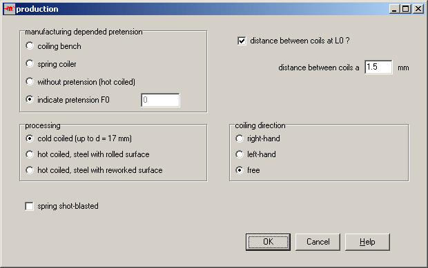
Normally, extension springs are coiled adjacent, cold-formed springs with pretension between coils, so that you need a force higher than pretension load F0 to extend the spring. With the new release 13.0 of FED2+, you can also define a distance a between the coils to calculate this special spring type (at Edit -> Production). If you input coil distance a, pretension tau0 and preload F0 are set to 0, length of spring body LK and all other spring lengths increase by n * a (number of coils x coil distance).
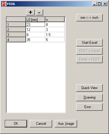

When entering spring sections for recalculation of a cylindrical nonlinear compression spring, you can now choose the input method: standard (separate sections), table, and Microsoft Excel. When entering spring sections in table or Excel, you may use buttons "Quick View" and "Drawing" to display actual spring. For dimensioning by input of the characteristic line of spring, this option is not available: spring sections first has to be calculated in this case.