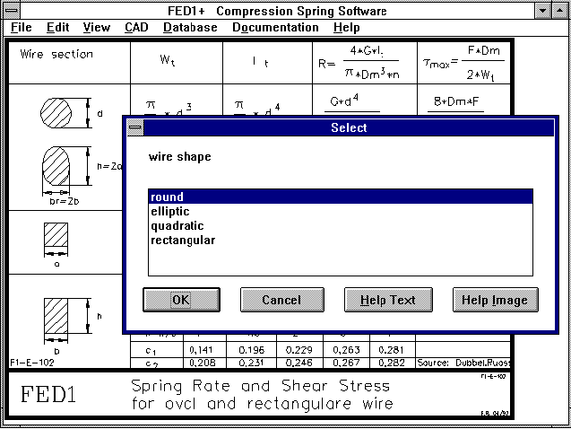
With FED1+ version 13.0 (not FED1), you can set the wire cross-section to round, square, rectangular and elliptical under "calculation method". If you wish to select rectangular or elliptical cross-sections, then you will need to enter the wire width b and wire height h instead of wire diameter d, under "dimensioning" and "recalculation". Spring dimensions and stress will be calculated for the required wire cross-section.
Output of spring drawing and manufacturing drawing is only possible for a round wire cross-section.
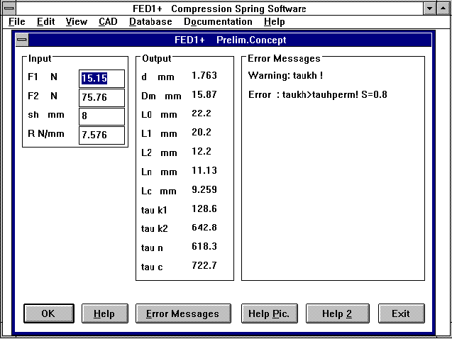
FED1 and FED1+ now have new "dimensioning" for the event that it is possible to freely define spring length L2 and coil diameter Dm. The program calculates an optimum usage spring with L2=Ln-Tolerance F2 / R. The spring characteristic curve reflects that the maximum spring force (F2 + upper tolerance) line is on the line for usable spring force. The coil ratio (coil diameter Dm/wire diameter d) is set to 9, the spring is calculated so that at a spring setting of 2, 70% of the permissible shearing stress is attained (tau2 = 0.7*tauzul). The safety margins are low with this type of dimensioning and the danger of settling is high. The endurance limit should be checked separately. Dimensioning of springs when entering the material shearing modulus can be found under "Edit->Dimensioning Material", it was previously under "Edit->Pre-dimensioning".
Shot blasting springs is pointless when the distance between the spring coils is smaller than the wire diameter. The surface of the highest stressed coil inner side cannot be reached by the blasting. FED1 and FED1+ provide a warning to this effect "Si0 < d!". I would like to thank Marc Reiber of Reiber Precision Springs in Rodgau, Germany for this information.
Coefficients are provided with the warnings when the minimum coil
distance is fallen short of, or when permissible shearing stress is
exceeded:
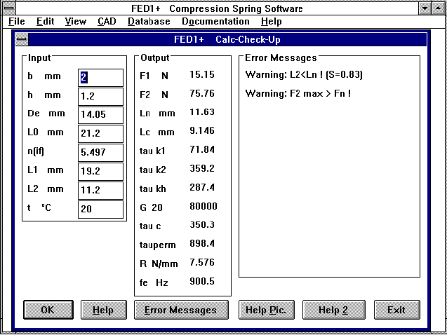
Warning: L2>Ln (S=x.x): S=(L2-Lc)/Sa is displayed.
S=1 for L2=Ln, S=0 for L2=Lc.
Warning: Danger of Settling !:
Warning, when tau2>0.7*tauzul. In addition, the factor tau2/tauzul
is now displayed.
Warning taun>tauz,tauc>tauz: S=tauz/taun
or tauz/tauc
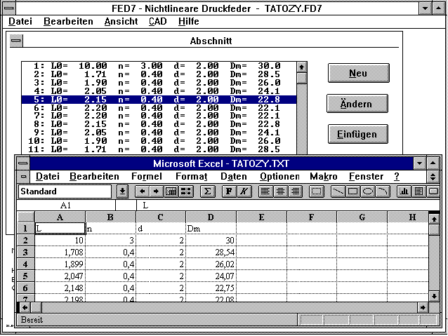
You can now import, calculate, change and save the table with L, n, d, Dm for the coil sections and and reexport to FED7 from Excel, Quattro Pro, StarOffice or other spreadsheet programs. This is especially useful when the spring form you require cannot be made up of the available FED7 types (cylindrical, conical, barrel shaped, waisted). This is where you can program the formula for reduction of a wire diameter and then export the table to FED7. Text format is used with tabs to separate the tabular values.
When, due to small tolerances (finer than quality degree 1), a 100% check, with sorting out of spoilage must be carried out, considerably higher costs are the result. This increases even further when additional criteria such as F1, F2 and Dm must also be checked. Until now, the sum of additional costs in the program was too low. I would like to thank Mr Bach of Wandfluh in Frutigen, Switzerland for pointing this out. The program now uses the most unfavourable conditions, e.g.: For a spring a 100% check is required for F1, F2 and Dm. Each additional check costs one Mark. F1 and F2 were okay, Dm wasn't. When F1, F2 and Dm are checked in that order, the cost will be three Marks. If Dm had been checked first then the costs for checking would have only been one Mark. FED1+ and FED2+ now calculate the most unfavourable case, in this case the costs would be three Marks.
The set option for calculating n (L0 variable) is not effective here, otherwise the spring length couldn't be altered.

A new auxiliary picture has been created within the scope of the FED1+ further development which now includes rectangular, square and elliptical wire cross-sections. The new auxiliary picture includes the formula for calculation of the spring rate and shearing stress for spiral springs with different wire forms. As spiral screw springs are loaded by torsion, the spring rate for rectangular wire remains the same when h and b are swapped. This is different with spiral springs as they are loaded by bending. The highest shearing stress occurs at the edges, at the weakest point, for rectangular and elliptical cross-sections loaded by torsion.
The block length is calculated with the formulas from DIN 2089, e.g. for ground coils:
Lc <= dmax * nt
with dmax = wire diameter + upper tolerance and nt=total no. of coils. As the calculated value is the maximum block length, new versions of FED1+ and FED6 also calculate and provide minus tolerances.
Lc min = dmin * nt
the tolerance is then
- tol * nt (*2)
For this tip I would like to thank Mr Jochim of Hydraulik Ring.
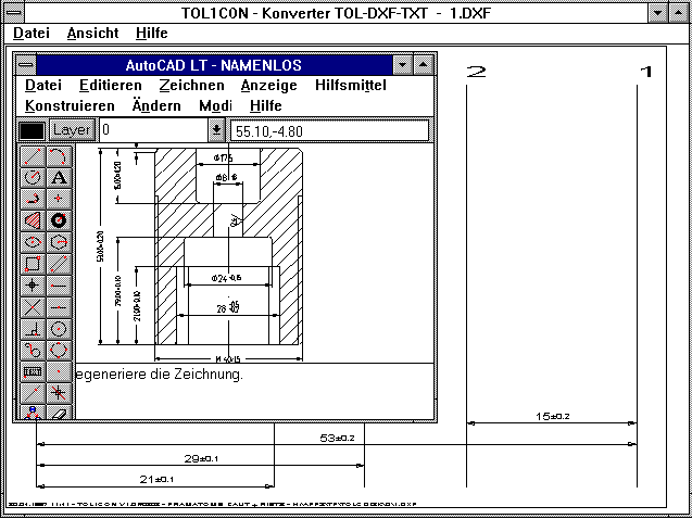
Until now the measurements had to be taken from the drawing and entered into the element table in TOL1 in order to carry out a calculation. With TOL1CON the drawing elements can be taken directly from a DXF file. This requires the measurements in the DXF file to be defined as "DIMENSION". You create a partial drawing of your CAD drawing by deleting the views and drawing elements not required for the tolerance calculation, the partial drawing then only shows the required drawing elements and measurements. This partial drawing should then be saved as a DXF file. In TOL1CON you select the horizontal or vertical elements from the DXF file and load them. You then select the root element 0 from a list of displayed elements. TOL1CON then loads all the horizontal or vertical lines and attempts to link the measurements to the appropriate measurement lines. In order to adjust possible deviations between the measurement lines and element lines, you can enter a band width (catch window). TOL1CON works out the relation between elements and creates an element list which can be saved in TOL1 format. Nevertheless, adjustment may be necessary at times. TOL1CON cannot tell when two or more measurement elements are on the same level. All measurements at this level will then be appointed to the same measurement element.
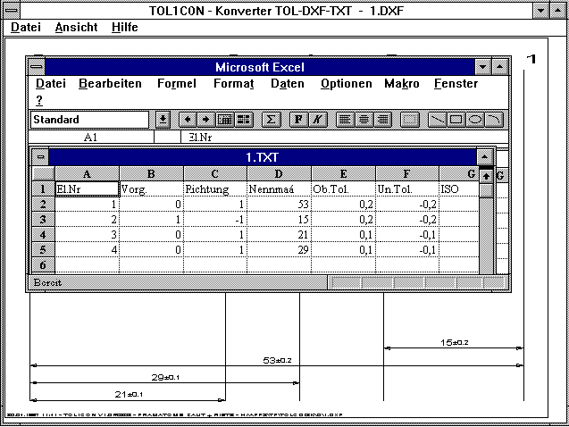
TOL1CON provides an interface between TOL1 and spreadsheet programs such as Excel, Quattro Pro and StarOffice. You can open a TOL file in TOL1 format and save it in TXT format. The reverse is also true, you can create a tolerance table with Excel and save it as a TXT table, then convert it to a TOL file with TOL1CON. TXT is used as the format (text format, columns separated with tab) which is supported by most spreadsheet programs.
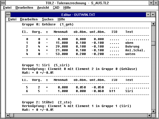
With TOL1 you can calculate the greatest and smallest measuremnt of any distance as a measurement chain. All measurements and tolerances are included in one working sheet. When one assembly part is used in several machines or assembly units, the data must be included in all working sheets. This is especially work intensive and prone to errors when changes are made to measurements or tolerances as all working sheets must be altered. With the new TOL2 program several TOL1 files can be joined to make up one assembly unit. TOL1 is now only used for single parts, which are joined by TOL2 to make up assembly units. For the application example in the TOL1 manual, six TOL1 files (housing, pestle, switch, locking ring, switch and cover) are created. Then you go to TOL2 and first define the housing as the root group (analogue element 0 in TOL1). Then enter the links for the switch position "on": Element 1 in group pestle with Element 0 in group housing, then Element 0 in group switch with Element 3 in group housing, and so on. For the switch position "off" the link occurs via pestle, locking ring, housing, in the position "in" the switch path is limited by the link pestle-housing. TOL2 can only be used with TOL1 (unless you create the TOL files with a text editor).
Consists of TOL1, TOL2, TOL1CON and TOLPASS available as our "Tolerance Package" at a price of 1,850 DM. If you already have TOL1 with a license number smaller than 250, and you have filled out and sent back the license agreement, then you can obtain an upgrade to Tolerance Package at a special price of 990 DM.
The use of hexagon flange screws reduces the effective surface pressure between the screw head and clamping piece due to lower contact surface, this results in a more favourable stress range. The data base "FLANGESC.DBF" now includes metric hex flange screws in accordance with IFI 536 and metric heavy hex flange screws in accordance with IFI 538. Many thanks to Ralph Shoberg of RS Technologies in Farmington Hills, USA for the data book "Metric Fastener Standards" from the Industrial Fasteners Institute.
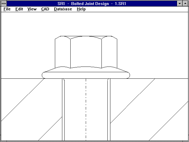
After tightening, the clamping pieces settle due to levelling off of the surface unevenness. The settling force loss is calculated from the settling amount. In accorance with VDI 2230, the settling amount is dependent upon the ratio of the clamping length to thread diameter and only very slightly dependent upon the surface unevenness. In strong contrast to this, the settling amount is independent of the clamping length and thread diameter according to Bauer & Schaurte. In the Table 1.14 in the Bolt-Vademecum, manufacture (turned/ground), load type (tension/pressure) and number of seams are included. With SR1 you can have the different methods calculated: By entering 0 you will get the settling amount according to VDI 2230. By entering -1 you will get the settling amount according to Bauer & Schaurte for turned clamping pieces and by entering -2 you will get the settling amount for ground surface. I would like to thank Mr Faulhaber of Linde in Aschaffenburg, Germany for this information.
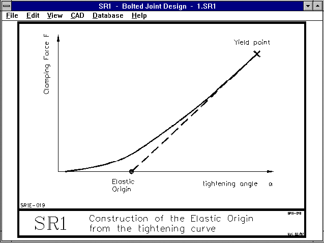
Due to input from Ralph Shoberg, who is the dealer in the USA and world wide for our SR1 Software combinded with his hard and software for bolt joint analysis, we have created an auxiliary picture for the tightening line. With RS Technologies' analysis machines the rotation angle-torque course for the tightening procedure is displayed. A tangent is shown on the curve of the linear part, this provides the elastic starting point. When the measured curves are not identical to the M-alpha-diagram provided by SR1, the cause is usually due to the strewing of the friction co-value for head and thread friction.
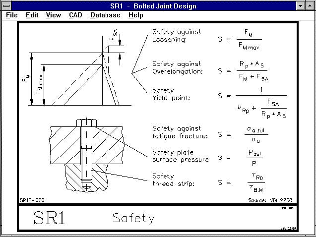
Safety margins against loosening, thread stripping, yield point, fracture, and permissible surface pressure are calculated by SR1. The formulae are shown in the auxiliary picture.
WL1+ uses the files "WL1WST.DBF" and "WST1DYN.DBF" for the material data. WST1DYN.DBF contains values for fatigue stress and comes from the WST1 material data base. Both data bases are linked by an identity number. Display of fatigue stress values and calculation of safety marings is only possible when an entry under the same identitity number exists in WL1WST and WST1DYN. You can now append and alter both data bases in the data base menu. For this information I would like to thank Mr Schuerer of German Mine Technology in Luenen, Germany.
The torque on the pinion has until now been limited to 100,000 Nm. The permissible entry range has now been extended to a maximum of 10^7 Nm. I would like to thank Mr Andersen of Waertsilae Propulsion in Norway for this information.
The SETUP program for installing Windows programs now also supports a deeper directory structure, e.g.: C:\PROGRAMS\HEXAGON\FED1. However, only the last directory (e.g. FED1) is created by the SETUP program, the other directories must already exist (here \PROGRAMS\HEXAGON).