HEXAGON Info No. 41 Jan./Feb. 1997


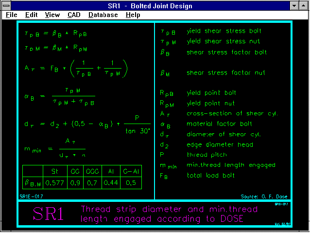
SR1 - Dose Formula

For blind hole threads the necessary minimum screw-in depth is calculated with the formula according to Dose. An error message appears when this is fallen short of. The safety against thread stripping for the forces FM and FSA has been added to Output. The safety against thread stripping with Rp is also calculated. This must only be greater than one, when the requirement is set that when overload occurs the bolt breaks instead of the thread being stripped. We would like to thank Dipl.Engin. Gerhard Friedrich Dose for this idea and the documentation.

SR1 - Bolt Material

Until now the bolt material could only be selected from the strength classes 12.9 thru 3.6. In the newest version, 6.0, the bolt material is selected from a list. The appropriate data base can be appended by the user.

SR1 - Material for Nut Thread

The material for the nut thread can be selected from the extended data base which is also used for clamping pieces. This made extension of the data base PRESSUNG.DBF necessary, and it now includes the fields RE (yield point) and BETA_B (shearing stress factor). The data base also includes a field, T_ALPHA, with the heat expansion co-efficient, for a later program extension which will include different temperature conditions.

SR1 - Safety Yield Point

The newly included safety against breakage, as mentioned in the last info letter, has been removed, as this is covered by the safety against over-extension. In its place, safety against exceeding the yield point due to additional bolt force FSA, has now been added to the program. In accordance with VDI 2230 the following apply:
FSA < (1-nü Rp)*Rp0.2*AS

If the conditions are not met, SR1 will provide the message "Yield point exceeded". An additional "safety factor yield point" results from this provision, with
           1
 S = ----------------------
              Rp0.2 * AS
      nü Rp + -----------
                  FSA
Nü Rp is the tightening factor in relation to the yield point. When the bolt is tightened to the yield point, nü RP is equal to one. Due to the FSA's share of the working force, the safety factor is smaller than one when the bolt is loaded above the yield point.

SR1 - English Threads

The data bases for threads and socket head cap screws have been appended with English threads. The GEWINDE.DBF data base structure has been altered, a new data field includes the thread description, for example M12x1.25. The fields for the stress cross-section AS and the core diameter D3 have been dropped as the program calculates them from nominal diameter and gradient.

SR1 - Total Drive Factor K

In the USA, pre-dimensioning does not differentiate between head friction and thread friction. The tightening moment is calculated with the simple formula:
T = K * d * F
The factor K can be calculated from æG, æK and the thread dimensions, this is now provided in the newest SR1 version. We would like to thank Mr Shoberg of RS Technologies for this information.
WN1 - Seam Play

The necessary seam temperature for cross-pressed fits is obtained from the maximum rappage and heat expansion co-efficients. In accordance with DIN 7190 a seam play of 0.001*DF is added to the maximum rappage in order to prevent adhesion during the seaming process. The factor 0.001 applies to individual manufacturing. For serial manufacturing this factor can be reduced with the appropriate manufacturing method, and with that, the seam temperature can be kept lower. In WN1 the seam play factor can be entered under "Edit-Temperature". We would like to thank Mr Pettersson of Volvo Trucks in Göteborg/Sweden for drawing our attention to this.

HPGLMAN/HPGLVIEW - Configuration

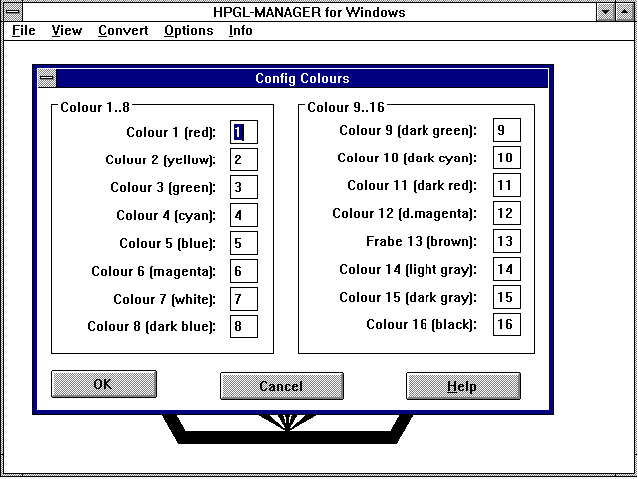
With the new HPGL Manager version you can reconfigure the screen colors. Version 2.0 now includes configuration of graphic, printer, directory paths and colors. The shareware version does not include these features.

HPGLVIEW - Late Success

For several weeks now the HPGLVIEW Demo/Shareware has been the absolute download hit in our internet pages. In the last four weeks the English version has been downloaded more than 400 times and the German version over 90 times. However, the sales figures are very modest. The program was sold only ten times from 1994 to 1996 at a price of 225DM. Our customer, Goss Graphic Systems in England, has ordered 20 versions for use under Windows 95 and NT as a viewer for the drawings from a mainframe CAD system. Our customer is so pleased with the program that they have ordered another 100 copies of HPGLVIEW for their construction, purchasing, sales and production departments. Our customer uses our HPGL Manager software for conversion of thousands of drawings into the compact HPGL/2 format. The employees can access the drawing archives via the PC network. The required drawing number is mouse clicked and then appears in the HPGLVIEW window on screen. A zoom window can be marked with the mouse. The area shown on screen can be printed out on any Windows' printer. If each department can do without its cabinet of drawing blueprints the savings with a "paperless" drawing administration are enormous. In addition to this there is also the environment aspect. Exchanging drawings when changes are made is no longer necessary. Updating of HPGL/2 files can be automated in the PC network.

DXFPLOT for Windows

Until now we have only provided a DOS version of our DXFPLOT software (also for use with Windows programs). Since the program works in the background it makes no difference whether it is for DOS or Windows. However, since in a few cases the program doesn't seem to work properly, we are now offering a Windows version. For example, in one case the manufacturing drawings in FED1/FED1+ could only be plotted once or twice and then no more. There seem to be memory problems with applications running in a DOS window under Windows. This error no longer occurs with version compiled under Windows. We are offering the Windows update at a price of 60DM, the normal additional charge of 60DM for the Windows conversion does not apply here.

Drawings with Company Logo

In order to create manufacturing drawings with your own company logo in the write protected file $LOGO_1.DX$, the spring program temporary directory and the DXFPLOT directory must be the same. Until now the temporary directory for DXFPLOT is the one in which it is called-up, in other words the working directory for the spring program. Output of company logo only worked when the working directory and spring program temporary directory were identical. In the new DXFPLOT versions and the Windows version the temporary directory is the path from which the file "DXFPLOT.DXF" is loaded. This allows different configurations for the working and temporary directories.

Graphic Printout - Ident-Line

All graphic printouts now include date, time, program, version and license number, as well as file name and path in the lower left hand corner of the graphic.

Printout Compressed

In printer configuration you can now configure a compressed printout. The separating lines are removed and the printout fits on one page instead of two.

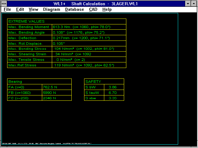
WL1+ Quick Output

The extreme values and bearing forces are displayed in a table under "View->Quick". This enables quick viewing of changes when optimizing a shaft. We would like to thank Mr Voss of Hoechst Diafoil for this suggestion.

WL1+ Iteration Factor

For the calculation of statically undefined mounted shafts an iteration factor can be altered under "Edit-Calculation" when a bearing is not taken into account, when the zero passes do not go through the bearing position or when the calculation time is too great.

WL1+ Configuration of Accuracy

The shaft is divided up into sections for the calculation. With the DOS version there are 300 sections and in the Windows version there are 600 sections. In the Windows version the number has been increased to a maximum of 2500. The calculation is therefore more accurate and narrow recesses no longer so easily drop through the net. Since the increase in accuracy also increases calculation time, this can be set under "Edit->Calculation". For statically undefined mounted shafts we recommend, in view of the calculation time, that you first set the resolution at 200 and increase to the maximum for the final calculation. In the DOS version it is not possible to go above 300 sections due to memory restrictions. We would like to thank Mr Gross of Heidelberg Pressure Machines for these suggestions.

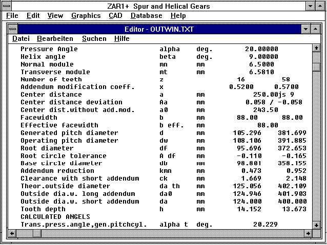
ZAR1+ Animation

The rotation direction of the animation has been corrected. For the sketched contact line Gear 1 drives clockwise. I would like to thank Mrs Professor Rosenberger of the Highschool for Technology in Leipzig for pointing this out.

FED Quick Input

The input for the most important dimensioning data in the Windows version of the spring programs is now under "Edit->Quick" instead of "File->New". All changes are now deleted under "File->New", the system date is used as creation date. If available, the "NULL" file is loaded for the default values. If you prefer not to have the old values appear when dimensioning a new spring, you can delete all the values and save this as a file with the name "NULL". This file will then automatically be loaded each time you start the program.

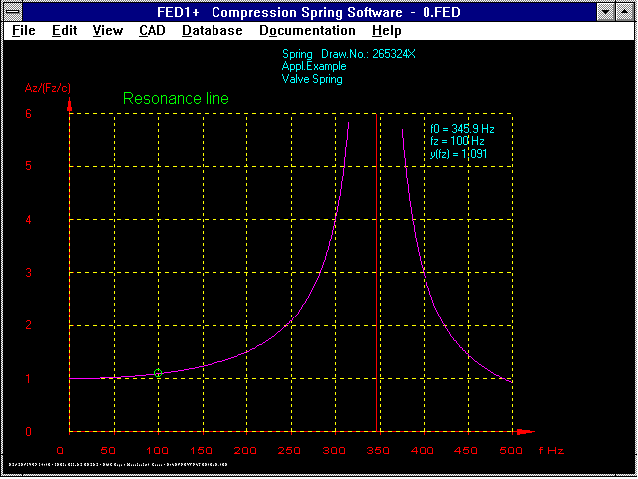
FED1+/FED2+ Frequency/Amplitude Curve

When the repetition frequency is close to the natural frequency, dangerous overshooting occurs due to resonance. You can now have the spring resonance curve displayed for dynamically loaded springs.

FED1/FED1+ Life Expectancy

A program crash could occur during life expectancy calculation caused by numeric overflow due to entering values which resulted in a spring with the safety margins çkhzul/çkh smaller than 0.001. The life expectancy is now set to zero for safety margins smaller than 0.001, so a program crash no longer occurs.

FED1/FED1+ Natural Frequency

The natural frequency is now provided in the output field for the recalculation.

FED1/FED1+ Calculation Method

Until now F1 has been recalculated by entering the spring rate R during dimensioning. It is now possible under "Calculation Method" to configure whether F2 or the lift sh should be adjusted.

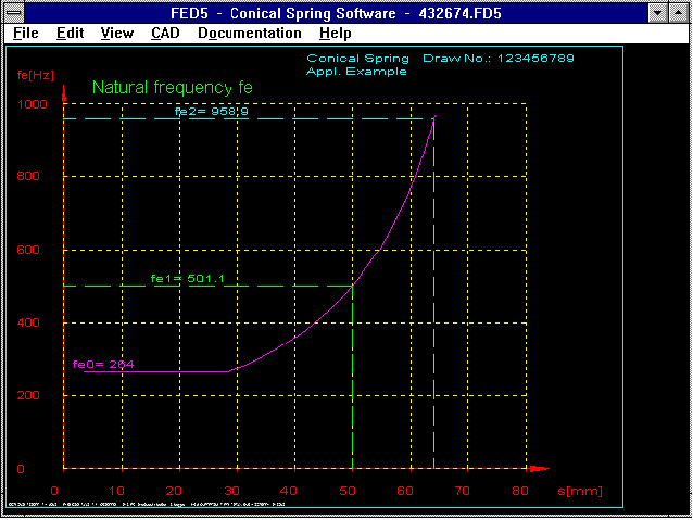
FED5 - Natural Frequency

FED5 software now also calculates the natural frequency of conical compression springs. In contrast to cylindrical spiral springs, the natural frequency for conical compression springs does not remain constant but alters along the spring path. As for the spring rate, the natural frequency remains constant until the large coils begin to flatten. The flattened coils are solid and have no influence on vibration, the natural frequency is calculated from the remaining springy part of the spring. For large spring paths the coil diameter and the number of springy coils becomes smaller and smaller, resulting in an increase in natural frequency. The natural frequency for L0, L1, L2 and Lc is calculated by FED5. The curve can be shown as a function of the spring path in a diagram.

WN3 - Calculation according to Niemann and 3892 Method C

The WN3 software for sliding key calculation now includes in addition to the DIN 3892 calculation method B, also the method C and Niemann method. Alternating load (reversing operation) is now only calculated according to Method B. For the calculated safety marings, deviations of up to 300% are obtained. This is caused mostly by the differing assumptions for the permissible surface pressue: For method B the permissible surface pressure is greater or at least the same as the yield point, method C calculates with pzul=0.9*Re, and the Niemann method allows 90 N/mmý for St hubs and 50/mmý for GG hubs!

WN2 - Permissible Torque acc. to Niemann

Along with the DIN 5466 and Roloff/Matek methods for calculating the permissible torque, the Niemann method has now also been included in the program. As with the sliding key calculation the main difference is in the permissible surface pressure. WN2 calculates with 60 for GG hubs and with 100 N/mmý for St hubs. According to Niemann p=200N/mmý is permissible in individual cases, in these "individual cases" the torque can be raised by 100%. The Roloff/Matek method provides the permissible torque for pulsating and alternating load. On the other hand, Niemann differentiates between the permissible torque for high and low impact operation. It is probably confusing that the program provides three different results for the same calculation, which, depending on the case, can differ greatly from each other. The calculation according to Niemann for shaft/hub joints is an approximate calculation which, due to the low permissible surface pressure still errs on the safe side. For the DIN calculations, many more criteria are required, along with torque, the axial force, bending moment, material factors, shaft and hub geometry, application factors. The Roloff/Matek calculations lie in between.

FED7 - Stress Curve

FED7 shows the shearing stress curve along the spring length in a diagram, prior to this the clamping length is required. The stress curve can look completely different for the same spring when the spring length is close to L0 and shortly before blocking.

FED7 - Animation Scheme and Spring

A pressure spring animiation of any shape is possible for the scheme diagram of the alternate cylinder and in the step by step approximation of the actual spring.

FED7 - Conical Compression Spring

When calculating conical compression springs, the coil distance can be continually increased or decreased by the factor nn/n1 (ratio of partial coil number of last to first section). By increasing the distance between the largest coils the linear area of the characteristic curve is increased.

FED1+ Excerpt with e1 and e2

The permissible plan and cylinder deviations e1 and e2 are now included in the excerpt.

Background Color

If you change the background color to blue or grey in the Windows programs, you should then redefine grey and blue under the settings for layers and colors otherwise they will no longer be visible. There are no problems with black or white background as these colors are not used for layers and colors. 3CFG Files in C:\HEXAGON1 All programs load the set configuration into the working directory from the CFG file. If the CFG file is not in the working directory, then standard values will be used. This isn't very practical with the Windows version when the link has been defined with the file extension and the HEXAGON programs are to be started by clicking on the file. In this case the working directory is the path in which the file is located. For this reason a change has been made: If the CFG file cannot be found in the working directory, the program will search in C:\HEXAGON. If you want to start your programs by clicking on the file, then you should create a HEXAGON directory in your C dirve and copy all CFG files into it. We would like to thank Dr. Moser of Siemens SGP in Graz for this suggestion.

DDEPROGM - Automated Progman Setup

For our customers with network installations we are now able to offer a software tool which automates creation of links between the different work stations. Especially with Windows' floating licenses, where the programs are to be available for many users, it is some what laborious and time consuming creating groups, icons and links for the program files in the network under the Windows Program Manager for all work stations. This has to be done individually for each work station because the configuration files (WIN.INI, SYSTEM.INI) are usually located on the local hard drive. With a "one-time" call up of DDEPROGM a program group with all HEXAGON programs will be created. The program also creates the links to the file extensions. The control file "DDEPROGM.MAK" can be used to define which program belongs to which path. You can download the program from our Mailbox or the Internet (use the password from the info letter). Customers with several network licences can obtain a free disk from us.

DBROWSE - Data Base Tool

Due to large changes and extensions of data base files, use of the included data base becomes some what laborious because only 3-6 lines can be shown on screen at one time. You can replace the internal data base with an external, more comfortable data base under "File->Settings->External Programs". For this we provide our cost free DBROWSE software. You can find the program DBROWS16.EXE (for Windows 3.1) and DBROWSE32.EXE (for Windows 95 and NT). in the Internet and on our Mailboxes. DBROWS16 also works with Windows 95 and NT, however, DBROWS32 does not work under Windows 3.1! The DBROWSE32 programs are packed together in a Setup program which also installs the required Borland Database Engine (the Database Engine run-time version has been released for passing on by Borland).

DOC files in the Internet

You can now call up information about the versions and current program changes from the DOC files via the Internet under "Customer Support->Updates and Further Developments" (German: "Support für Kunden->Updates und Weiterentwicklung). Please use the password in this letter, then you can read the development history for all programs. In this way you can easily decide if an update to your current version is of interest to you.

Seminars

In March 1997 we will again be offering seminars for gear calculation, spring calculation, working design calculation and certification in accordance with ISO 9001. If you are interested, please write or call for our seminar schedule.


Fritz Ruoss
HEXAGON Industriesoftware GmbH
Stiegelstrasse 8
D-73230 Kirchheim/Teck (Germany)
Tel.: 07021-59578
Fax: 07021-59986
Mailbox BBS: 07021-480015 (Modem 28800..2400bps)
Mailbox BBS: 07021-959242 (ISDN 64000bps)

Homepage