
FED1+: Point cloud as result of search run for springs in pre-defined installation space
At "Edit->Dimensioning installation space" you can now define installation space of the spring (L1, L2, Demax, Dimin) together with minimum and maximum values for spring load F1 and F2. Next, FED1+ calculates about 20,000 springs, done in less than one second. Results are marked in a point cloud. A red cross means that spring cannot be calculated, or block length is larger than assembly length. A red rhombus means that shear stress is higher than permissible shear stress. A yellow triangle shows a spring that is good for static use, but not fatigue-resisting. A magenta "<" marks a buckling spring, and a green circle stands for a suitable spring free of errors. Different symbols printed one upon the other stands for different springs with same coil and wire diameter but different load. The optimum springs for different aims are listed in a table:

A mouse click into a spring of the table with optimum springs opens the spring data and shows calculation results in the graphic window.
Installation space has been added to L2 spring drawings in Quick3 and Quick4 View.
FED1+: Increase of shear stress because of shock loading
At "Edit->Application", input of a collision velocity v,St has been added to calculate increase of shear stress tau1 and tau2 according to EN 13906-1:
tau,st = v,st * SQRT(2E-3 * density * shear module G)
Thus increase of shear stress for spring steel is about 35 N/mm˛ for 1 m/s.

FED1+, FED2+, FED3+, FED6: Goodman diagram with tolerance range

Tolerances of spring load or spring torque can increase or decrease stress tauk1 and tauk2 or Sigmaq1 and Sigmaq2. Goodman diagram now includes tolerance band limited by min and max values of tauk1 and tauk2. Min and max values for load cycles and life expectation are calculated and printed.
FED1+: Warning "aW0 > d" for safety springs
"Safety springs" are defined as compression springs with a coil distance less than wire diameter. This ensures that a broken spring cannot block the spring travel.

At "Edit->Calculation Method" you can set the option "Warning aW0 > d (safety spring)" to get a warning aW0 > d if the coil distance is larger than wire diameter.
FED1+, FED2+, FED3+: Base data with Calc button
A "Calc" button has been added to the input window with base data for immediate calculation and show results in background window.
Spring materials - Calculate E module from G module
A customer reports that E module of 1.4310 and 1.4401 differs between fedwst.dbf database and EN 10270-3. But G module is equal. E module in HEXAGON is 190 instead of 185 for 1.4310 and 185 instead of 180 for 1.4401.
However, under index a of the EN standard is written that the E module data are calculated from G module by this equation:
G = E/(2*(1+nue)) (2 brackets missing in the EN).
Then is E = G*(2*(1+nue)) = G * 2,6 with nue=0,3.
But 73000 * 2.6 is 189.800 MPa.
AGMA 18-8 even uses E = 193,000 MPa
Sandvik uses 190,000 MPa for heat-treated spring, and 185.000 in delivery state for 12R10
For 1.4401 makes 71000 * 2,6 = 184,600 MPa. HEXAGON database values prove to be correct, because of better conformity with conversion equation and manufacturer's information.
Data of "new" spring materials 1.4301, 1.4462 and 1.4539 of EN 10270-3:2011, however, have been added unchecked into fedwst.dbf database. Data of 1.4462 and 1.4539 are correct and conform to data sheet of Sandvik Springflex and Sandvik 2RK66.
But 1.4301 data in EN 10270-3:2011 must be called into question. Compared with 1.4310 (X10CrNi18-8), chemical composition is similar as 1.4301 (X5CrNi18-10). E module of 1.4301 is in EN higher, but G module lower as 1.4310! Calculated Poisson ratio is 0.4 for 1.4301. E module of 190 GPa is realistic, calculated G module with µ=0.3 is 73.000 MPa, same as for 1.4310.
If you have proven data for 1.4301, please let me know. Maybe the G module of 1.4301 in the fedwst.dbf database must be changed from 68000 MPa into 73000 Mpa.
New "CAD" output format STL
Output of STL files for 3D printers has been added to the CAD formats DXF and IGES.
STL is a 3D format. It is useful for profile drawings to generate a 3D volume. Examples of useful applications are spur gears, involute splines, serration profiles, splined shafts and hubs. Also profiles of GEO1+ and TR1, cams and cam disks of GEO4, noncircular gears of ZAR4, spiral springs of FED9.

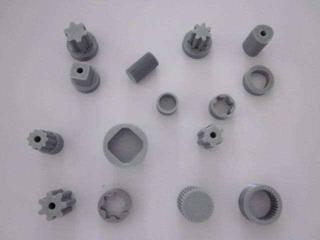
ZAR1+, ZAR4, ZAR5, ZARXP, ZAR1W: Spur gears made by 3D printer

STL files of ZAR1+, ZAR5, ZARXP or ZAR1W can be used to print spur gears on 3D printer for prototypes and models. Which settings and tolerances should be used depends on hardware, material, nozzle diameter, processing temperature, shrinkage and so on. My first spur gears for a planetary gear set printed by "Ultimaker 2+" with PLA filament clamped in the ring gear, flank tolerance "e25" to DIN 3967 was not functional for 3D printed gears. New printed gears with large flank tolerance "a 29" ran with sufficient clearance. For noncircular gears created by ZAR4, flank clearance is adjusted by center distance.
ZAR1+, ZAR5, ZARXP, ZAR1W: STL Menu and bore diameter
A bore diameter can now be defined for the gear wheels. For ring gears, "bore diameter" is the outer diameter of the hub. A new STL menu has been added to the gear calculation programs to print gear wheels directly as STL file. In ZAR5, also a simple planet carrier can be printed as STL file for 3D printer.


ZAR5: Mesh load factor K gamma
Mesh load factor considers inconstant load distribution of sun gear and ring gear with the planet wheels. Normally, Kgamma has to be considered only if more than 3 planet wheels are used. For 1, 2 or 3 planet wheels, set K gamma = 1.
ZAR1+, ZAR4, ZAR5: Error in ISO 6336-2:2006

Length of the first square root under the fraction bar is too short in equation (17) and (18) of ISO 6336-2:2006. That was the reason why single contact factors ZB and ZD are calculated much too large in spur gears (beta = 0 deg). In DIN 3990, the equation is correct.
A customer had complained about the difference between strength calculation to ISO 6336 and to DIN 3990 (>50%) for a planet gear set with spur gear wheels. Factor ZB appeared as the reason.

Another modification according to "Corrigendum 1:2008" of ISO 6336 has taken into account in the latest release: Helix angle factor Zß was replaced by its reciprocal value. Until now, and according to DIN 3990, Zß was always smaller than 1. Now it is always larger than 1.
WN7 – Enter P4C profile data directly

As alternative to select P4G profile from database, you now can directly enter the P4G parameters (outer circle diameter, inner circle diameter, eccentricity).
WN2, WN4, WN5, WN6, WN7, WN8, WN9, WN10: STL Menu
WN programs for calculations of shaft-hub connections got a STL menu to print toothed shaft and toothed hub on 3D printer. Where not available, input was extended by length of shaft and hub, bore diameter of shaft, and outside diameter of hub.
ZAR4 – Import DXF
Pitch curve of a noncircular gear can now also be imported from a DXF file. Pitch curve must be defined as one polyline.
Another new feature is a phi-R table with polar coordinates of the pitch curve. Phi-R table can be entered directly, or imported from Excel or any other Windows table. As option, ZAR4 calculates intermediate values by linear interpolation.
Application examples: Generate a P3G profile in WN6 as polyline, then load in ZAR4 as noncircular gear with P3G pitch curve. Or save a cam profile in GEO4 as DXF polyline, then load in ZAR4 as cam with involute teeth..

GEO4 – Cam profile as STL file
New STL menu generates cam or cam disk as STL file for 3D printers. Input of cam width and bore diameter has been added in an additional input window for cam dimensions.

GEO4 – Cam curve by polar coordinates

Cam curve can be entered as phi-R table of angle and radius of a polyline. As option, intermediate values can be calculated by GEO4.
Phi-R table can be imported from Excel or other table software via clipboard.
And a cam curve by DXF imported polyline can be edited in GEO4 as x-y table or phi-R table.
DXFMAN, HPGLMAN – Animation
New animation mode in DXFMAN and HPGLMAN decelerates display buildup of the drawing. So you can watch sequence and direction of lines, arcs and circles. This can be useful for conversion into CNC code or if drawing profile is used for milling, wire eroding, 3D printing etc.
Because arcs and circles used for drawings have no directions or are always printed against clockwise sense, better use polylines in your drawings.
In animation mode, you should not enter too large time interval between 2 points. Only 1 millisecond interval can prolong display buildup 1000 times.
DXFMAN, HPGLMAN – Convert to STL
2D DXF and HPGL files can be converted into STL Format.
DXFMAN, HPGLMAN – Open generated file by external program
Configuration of "Exec Viewer" runs external program after conversion and loads the converted file.
SR1+: STL Menu for 3D print of clamping plates and circular flange
Models of clamping plates and circular flange can be printed on 3D printer. A new STL menu also has been added into GEO1+ and TR1 for profiles, FED9 for spiral springs and FED10 for leaf springs and form springs.

Run CAD and STL Program automatically
If you saved a DXF or IGES file of your calculation, you next had to run the CAD program and search and open the file.
Now you can set the option "Exec CAD App ?" at "File->Settings->CAD" to run the CAD program and open the drawing file automatically.

Convert arc to polygon
For output as IGES, STL, or TXT file you can now configure to convert polyline arcs in into polygon lines. This can make sense if file is used for conversion into CNC, because arcs have no direction and are always drawn in mathematical positive direction (anti clockwise). Check "Polyline Arc->Lines?". Resolution in mm can be configured.
Suppress hints and warnings
Hints and warnings that only indicate that a value is outside of preferred zone may be annoying in the printout and therefor can be suppressed. Some of the programs already offered this option at "Edit->Calculation Method". Now this option has been added at "File->Settings->Settings" for all programs. However, error messages and severe warnings are always printed and cannot be suppressed.
Adapt window size and dialogue element size automatic
If you change screen resolution or font size in Windows settings, you had to adapt windows size and dialogue element size in the HEXAGON program, else you got input windows with scroll bars. Now you can configure to adapt window size and dialogue element size automatic. Window size can be set to max (full screen) or "max 4:3". A wide screen display (16:9 or 21:9) in "max" setting draws circles as ellipse, in "max 4:3" setting it is round. Default setting is now "max 4:3" for window size and "Automatic" for dialog element size.

Invalid license code without any changes
A new key code is required only if computer or hard drive was changed. If your HEXAGON software stops with key code error, maybe partitions have been changed on the hard disk. If not, you should check if a spy software reduced your partition to collect data on a hidden partition. It seems that Windows 10 updates modify partitions on the disk drive, too.
If the software stops with invalid key code error, delete .cod file. Then run again and send key code request by email.
DBFCOMP new release
A new release of the DBFCOMP tool to mix self-modified database files with HEXAGON updated database files is available. This tool is helpful only if you modified database files, and by an update you do not want to loose your self-defined records, nor abdicate the updated records delivered by HEXAGON.