FED1+ Smith Diagram
As alternative to Goodman diagram, Goodman-Haigh diagram and SN Diagram, FED1+ provides also a Smith diagram now. These four fatigue strength diagrams can now be found in a submenu under "View -> Fatigue Strength".
For helical springs, Smith diagram is not as convenient as Goodman diagram, because x-axis defines mean stress, which must be calculated (tau m = (tau k1 + tau k2) / 2). Smith diagram may be useful when comparing with material data sheets. Or for the special case, that a compression spring is used in both directions, compressive and tension.
FED8: Smith-Diagram

Torsion bars often are used with alternating load, spring angle alpha 1 is set negative and alpha 2 positive in this case. FED8 now shows a Smith diagram and calculates number of load cycles, if spring is not fatigue strength safe. Fatigue data are loaded from fedwst.dbf material database.
FED8: Quick3-View
New Quick3 view in FED8 shows dimensions and calculation results, load-torsion diagram and Smith diagram, spring drawing in front view and side view, altogether on one screen.

FED2+ Tension Spring without Loops

At Edit -> Loop, you can now also select "without loop" for to calculate and draw endless spring without loops.

FED1+ 2+ 3+ 5 6 7 8 9 11: New Materials GARBA 177 PH and GARBA 177 Supreme
GARBA 177 PH and GARBA 177 Supreme from Suzuki-Garphyttan are stainless, shaved spring steels for age-hardening, similar than 1.4568 and AISI 631, for applications with high and highest dynamic stress. Tensile strength of the GARBA materials is nearly equal than EN 10270-3-1.4568. Fatigue strength, however, is described much higher (up to 50% for PH and 60% for Supreme) compared with 1.4568 according to EN.


Goodman diagram of GARBA 177 PH and GARBA 177 Supreme for an example spring


Goodman diagrams of the same spring with EN 10270-3-1.4568 material: according to Goodman diagram from EN 13906-1, spring would break because of exceeding the maximum stress. If you set the option "tauoz = tauz = 0.56 Rm" at "Edit -> Calculation method", the 1.4568 spring is good for 400.000 load cyles. If you set the option "tauoz = tauz = 0.56 Rm" using the GARBA materials, fatigue strength becomes even lower, because maximum stress in the fatigue strength diagram is higher than permissible shear stress.
Other database modifications in material database fedwst.dbf: tensile strength limit (for small wire diameters) reduced for EN 10270-3-1.4568 and Sandvik 9RU10: Rmmax reduced from 2700 to 2400 and from 2600 to 2400 MPa.
FED1+ 2+ 3+ 5 6 7 8 9 11: Copper Alloy Wire updated in Material Database
Release 08-2011 of DIN EN 12166 affected tensile strength of copper alloys, which concern 4 such materials in fedwst.dbf material database. Tensile strength values in the new EN standard are lower than in the old release. Database was modified:
EN 12166-CuSn6-R980 → R900 (tensile strength Rm 900 Mpa)
EN 12166-CuZn36-R700: no changes at Rm, only at dmin/dmax
EN12166-CuBe2-R1310 → R1300 (tensile strength Rm 1300 Mpa)
EN12166-CuCo2Be-R750 → R730 (Rm 730 MPa)
Modifications concern only wire material. The corresponding standards DIN EN 1654 for strip steel (used in FED4, FED9, FED10, FED13) remained unchanged.
FED1+ 2+ 3+ 5 6 7 8 9 11: Wire Diameter Tolerance EN 12166 (copper alloy)

EN 12166 tolerance system has been added to the available tolerance systems. If you choose a EN 12166 material from database, EN 12166-A tolerance is set by default.
FED1+, FED6: Life Expectation in Brackets, if tauk2>tauz or L2<Ln or spring buckles
The life expectation calculated from fatigue strength data is valid only if permissible shear stress is not exceeded and spring is not buckling. Another reason that the calculated lifetime will not be reached can be that the safety distance Sa until block was not kept, and the spring fails because of coil collision. Calculated lifetime is printed in brackets in this cases. Coil distance aW2 in position 2 has been added to printout as help for estimating the remaining safety distance, if s2 > sn.

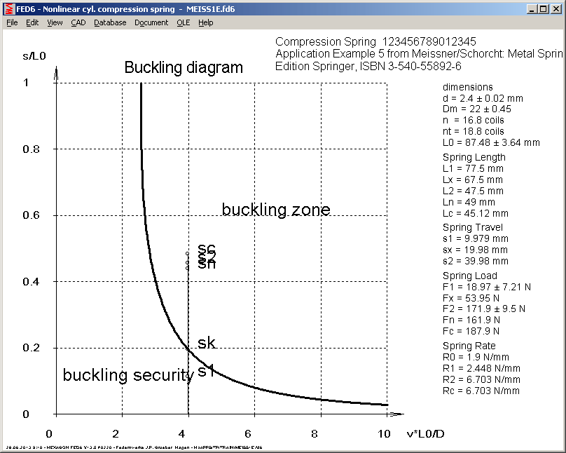
FED6: Buckling Diagram

New in FED6 is a buckling diagram and error messages if spring buckles.
FED6: Number of Active Coils
"Number of active coils" in printout has been renamed into "number of coils". This means the number of coils without end coils. And "total number of coils" means number of coils inclusive end coils. For progressive springs, number of active coils changes with the spring travel. And in FED6 you can define sections with inactive coils (L0i=ni*d). Number of active coils for position 0,1,2,x,n,c has been added to printout.


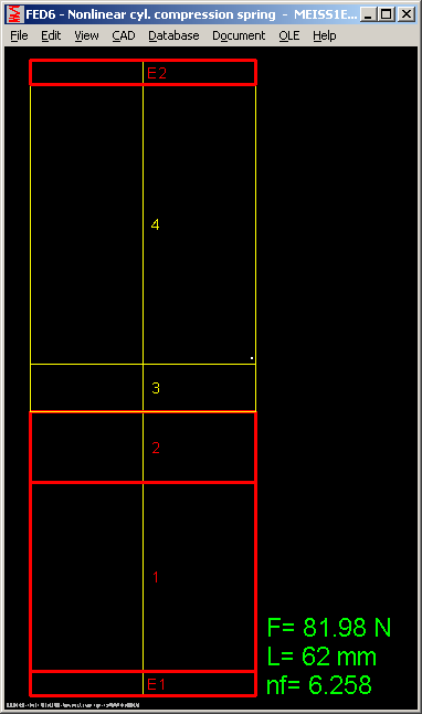
In the draft with spring sections and in animation, number of active coils nf is printed now. Yellow drawn sections are active coils, bold red drawn sections are inactive coils.

FED7: Quick4
New Quick4 View draws load-deflection diagram, Goodman chart, tables with spring sections and loads, spring drawings and coil drafts in position 0, 1, 2, c (block), altogether on one screen with A3 drawing header. To recognize the text, screen resolution should be at least 1400 x 1000 Pixels.

FED7: Production Drawing Quick3
Results, diagrams and drawings of Quick3 view, positioned within an A4 drawing header, is another new output feature of FED7.

FED4: Quick3 View
New Quick3 view in FED4 shows spring drawings, diagrams and results on one screen.

FED4: Friction

Friction increases required load to reach spring position. And when relieving load, disk spring remains in position until load is lower than spring load less friction load.

At "Edit -> Friction" you can now enter friction coefficients. Load-deflection curve with friction area and hysteresis is drawn in the diagram.
FED4: Spring Drawing hatched

At "View->Drawing", disk spring is drawn as section drawing hatched 45°
FED4: Goodman-Diagrams
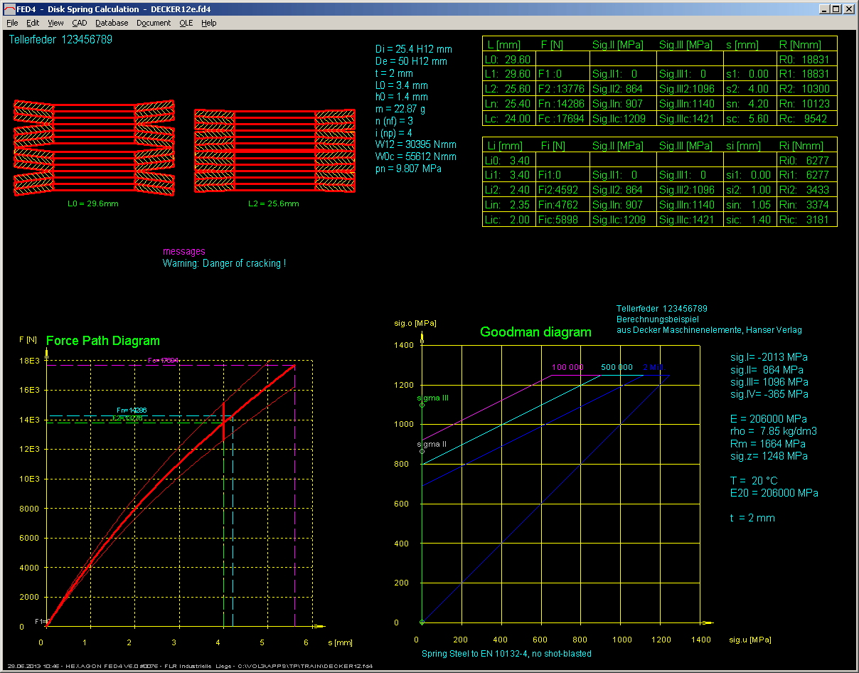
If you select a spring material according to DIN 2092, Goodman chart corresponds to DIN 2092. Goodman charts in DIN 2092 are for non-shot-peened disk springs. Because shot-peening increases permissible variation of stress for about 20%, Goodman diagrams have been modified now for the case that shot-peening is defined.
WN2+: Flank Tolerances and Addendum Modification
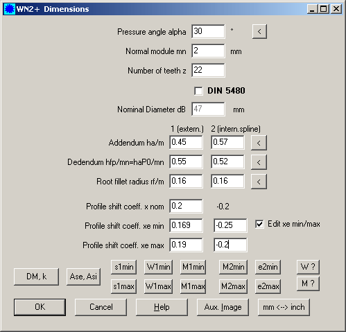
In the Plus Version of WN2, you could modify the nominal addendum modification coefficient x2 at "Edit -> Dimension Tooth", and choose a tolerance zone at "Edit->Quality".


This was modified and improved: nominal addendum modification coefficient is always x2 = -x1. Now you can input addendum modification coefficients xe2min and xe2max instead. Or you can directly input the tolerances Ase and Asi. Or you can input min and max value of dimension over pins or span measurement. Or you can input min and max value of tooth width and gap width.

ZAR1+: Quick3 View with MKnom and Material Number
Material name and material number is written in 2 lines now. Theoretical dimension over balls (nominal dimension without tolerances) has been added in Quick3 View.