 |
Deutsch
G E O 1 +
Software for calculation of cross-sections and profiles
(C) Copyright 1994-2025 by HEXAGON Software, Berlin
GEO1+ software calculates cross-section areas, surface moment of inertia, center of gravity and mass moment of inertia of any cross-section made up of up to 2000 lines and arcs.

Geometry Input and Calculation
The contour is defined by input of the y and z coordinates of the first and last point in the xyz coordinate system. For arcs the opening angle is also required. The outer contour is entered anti-clockwise, apertures and boreholes are entered clockwise. GEO1 calculates the cross-section surface, the axial surface moments 1 and 2, order, mixed and polar surface moment in
relation to coordinate origin and the center of gravity.
GEO1+ also calculates the main surface moments and the main angle of the coordinate system. The flat surface becomes a body by entering a contour length Lx and the material density. In this case GEO1 also calculates volume, mass and mass moment of inertia at the center of gravity and coordinate origin. For the calculation the arc and boreholes are divided up into
polygons, the accuracy can be set. The contour can also be imported as a polyline from a DXF file.
Graphic Output
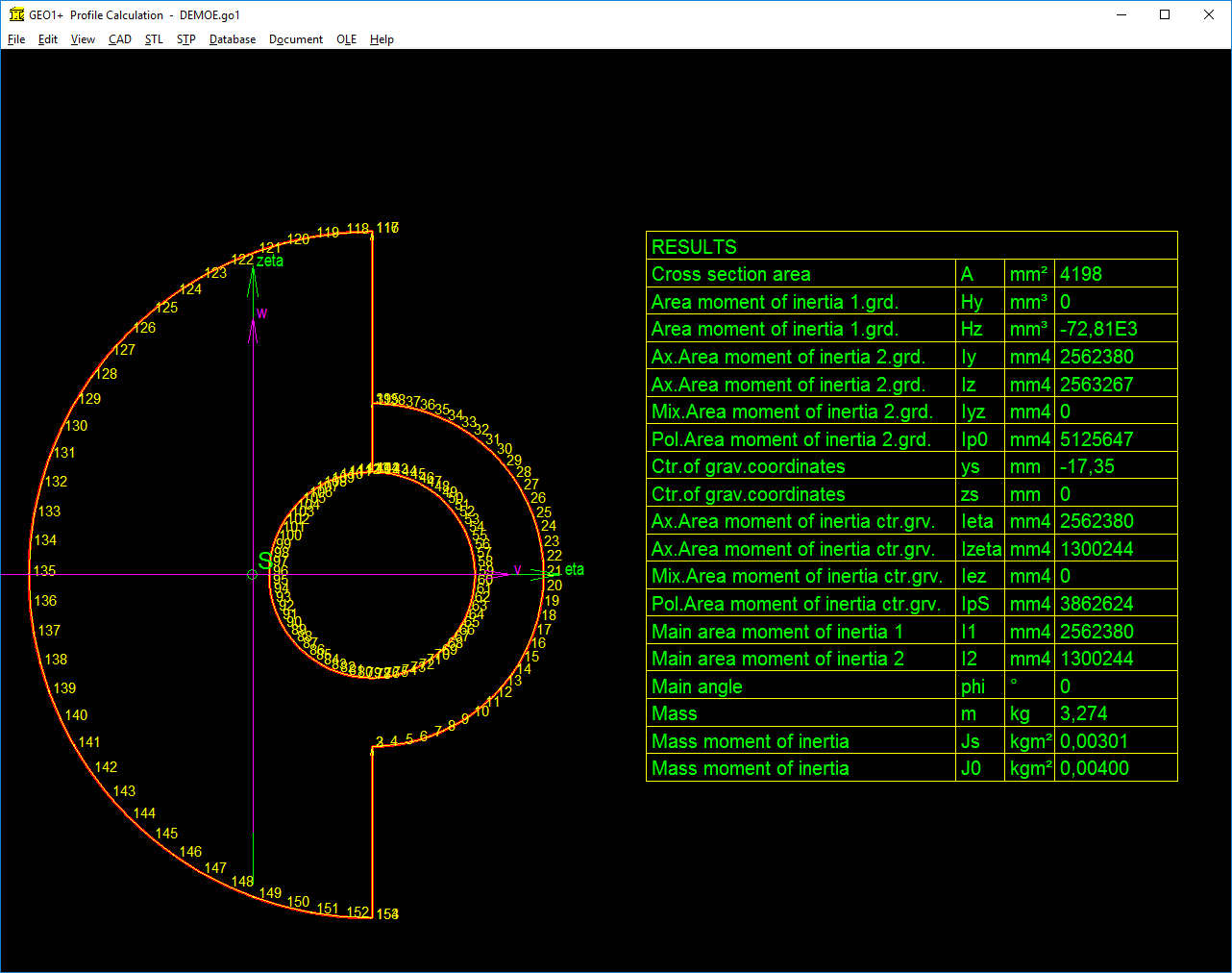
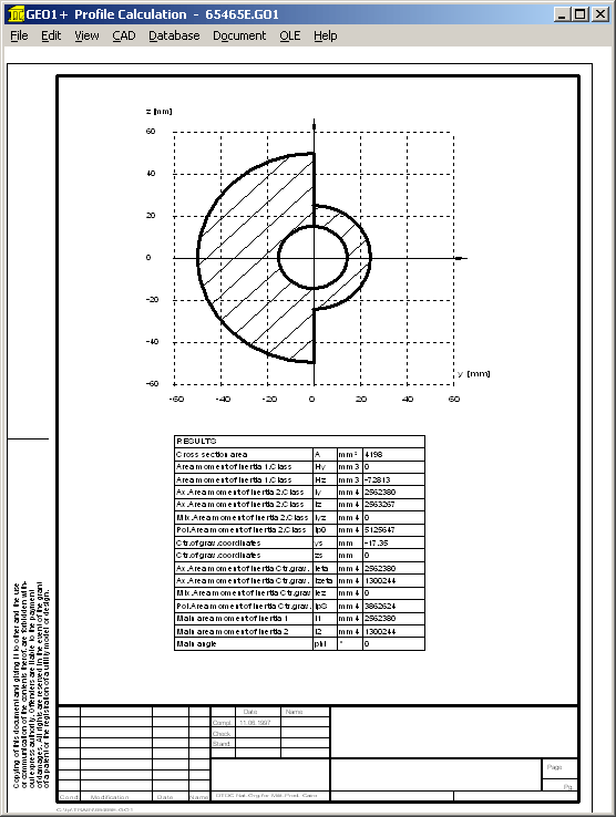
The entered contour is displayed as a graphic on screen along with the coordinates, center of gravity and main axes. The most important result data is shown in a table. The drawings can be output on needle, laser or inkjet printers.
HEXAGON Help System
For each input there is a help text and auxiliary picture available in the HEXAGON Help System. When error messages occur you can have a description and remedy suggestion for the error displayed.
CAD Interface
Geometry and result tables are generated by GEO1 as DXF or IGES files. This enables export to CAD systems or word-processing programs. On the other hand the contour need not be input in GEO1, but can be imported as a DXF file provided the contour has been drawn as a polyline (POLYLINE command).

GEO1+ Profile Database
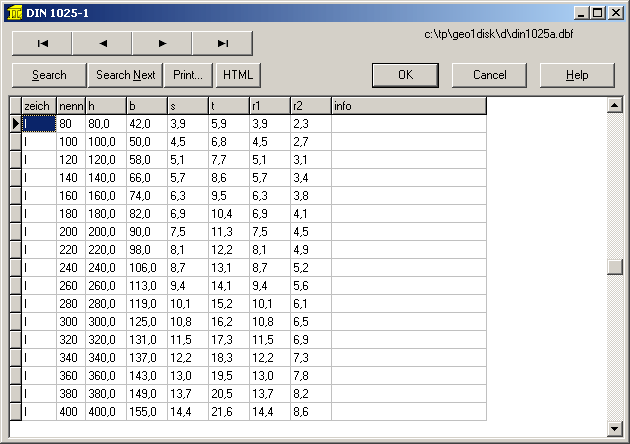
The extended Version GEO1+ contains databases with standard profiles according to DIN: T profiles to DIN 1024, double-T to DIN 1025, L-profile to DIN 1027, angular profile to DIN 1028, U profile to DIN 1026 and rectngular profile to DIN 1017 can be selected from GO1+ database.
GEO1+ generates coordinates from the database values and calculates cross-section.

Standard Profiles
For circular profile (shaft), tube, rectangular tube, polygon, polygon tube, sector of circle, sector of annulus, sector of annulus with bore, rectangle with bore, and circle with eccentric bore, just enter inner and outer width, diameters etc. and GEO1+ calculates coordinates and cross-section.
STL Interface
GEO1+ generates STL files to produce the profile directly on a 3D printer.
System Requirements
GEO1+ is available as 32-bit and 64-bit application for Windows 11, Windows 10, Windows 8, Windows 7.
Scope of delivery
GEO1+ program, sample data, auxiliary pictures and help text, input forms, user manual (pdf), license agreement for indefinate period of time.
Guarantee
HEXAGON gives a 24 month guarantee on full functionality of the software.
Information and Update Service
HEXAGON Software is continuously improved and updated. Customers are regularly informed about updates and new editions.
Pricelist |
Order |
E-Mail |
Home

 |
Deutsch


