FED1+, FED2+ Spring Length after Relaxation
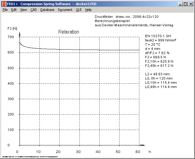
Spring software FED1+ and FED2+ calculates loss of spring load F2 after 10 hours and 48 h. You can calculate the unloaded spring length after relaxation from this value. Spring length L2 and spring rate R are constant, so the new unloaded spring length is:
L0,48h = L2 + F2,48h / R with FED1+ (compression spring)
L0,48h = L2 - F2,48h / R with FED2+ (extension spring)
Unloaded spring length after 10 h and 48 hours of load were added to relaxation diagram.
For spring manufacturers: If you want to calculate spring length after setting procedure, calculate with L2 = setting length, and working temperature = setting temperature.

FED1+,2+,5,6,7 - New Dialogue Window Relaxation
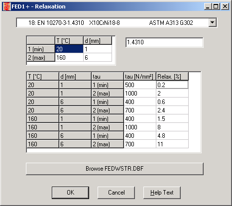
A new dialogue window simplifies input of relaxation data for self-defined materials. Relaxation database needs relaxation of load for two temperatures, two wire diameters, and two shear stresses (total of 8 values).
FED1+, FED2+ Spring Database
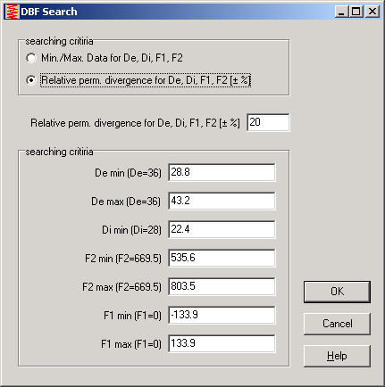
If you searched spring catalogue at "Database->Search for Spring", nothing was found if your spring load F1 was 0. For this case is L1=L0, but the program considered only springs with L0 > L1 (compression springs) or L0 < L1 (extension springs). Relative perm. Divergence for F1 is now calculated from F2, else tolerance would be 0.
FED3 - Auxiliary Picture
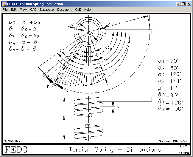
"GEOMETRY" image was improved, formulas and angles have been added for a better understanding.
FED3+ Production Drawing
Tolerances of leg angle delta 0 and torque was added to the production drawing, as well as mandrel diameter Dd.
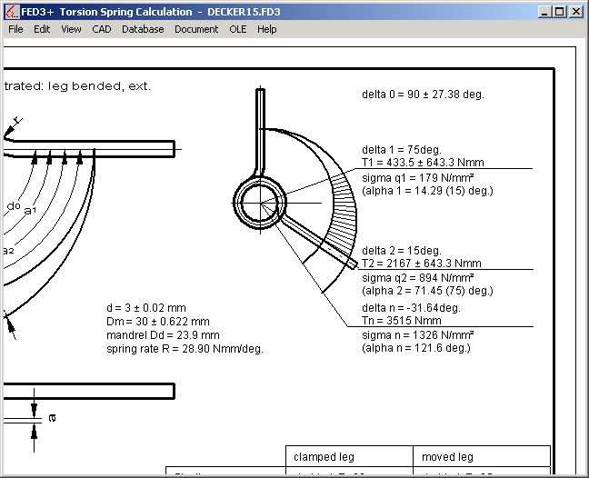
FED1, 2, 3 - Hidden Tolerances for Dimensions and Load
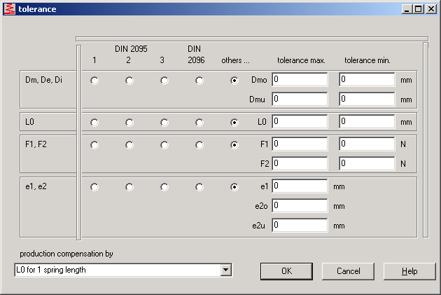
In the new versions of the spring programs you can set tolerances to 0 in order to hide tolerances in output and production drawing.
FED4 - h0
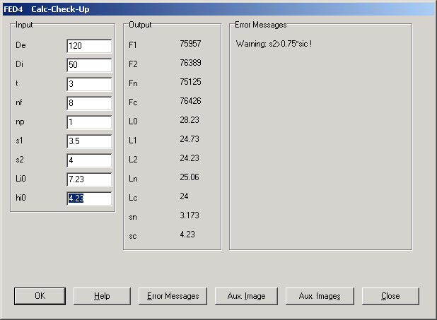
Instead of length L0, you can enter maximum spring travel h0 (=L0-t). The factor h0 / t (t = thickness) determines the type of the curve characteristic. For h0 / t = 1.41, spring load is constant at block length (spring rate Rc=0). If h0 > 1.41 * t, spring load declines after reaching its top load.
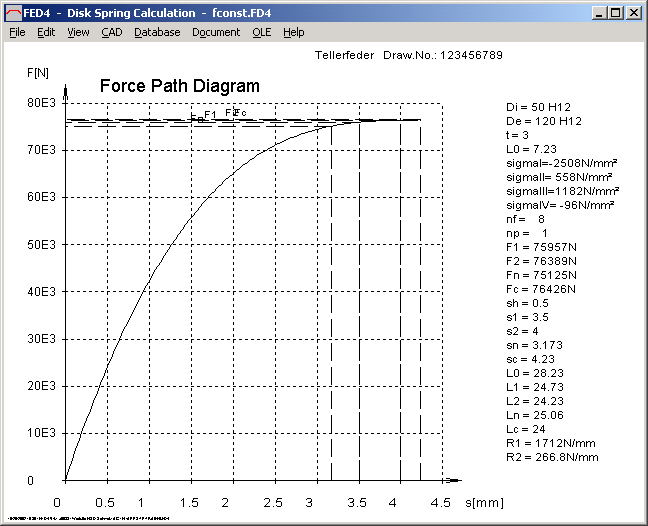
The working travel of the above disk spring with h0/t = 4.23 / 3 = 1.41 is between 3.5 and 4 mm. In this zone, spring load is approximately constant. Disk spring could be used as "constant load spring", i.e. to compensate temperature effects in bolted joints.
SR1 - Calculation Method
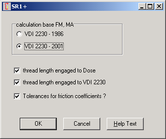
Now you can choose to calculate thread strip safety to Dose, to VDI 2230, or to both methods.
SR1 - Friction Coefficient w/o Tolerances
At "Edit->Calculation Method" you can choose if SR1 should calculate minimum tightening torque from friction tolerance and alpha_a or not.
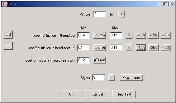
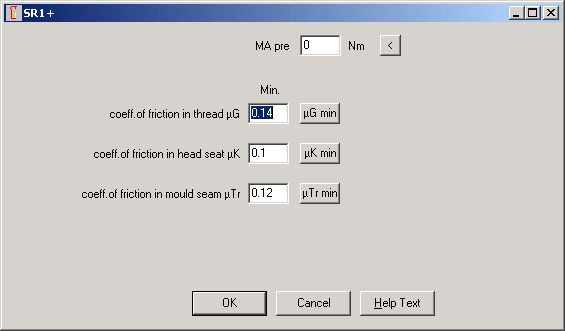
Friction tolerance disabled
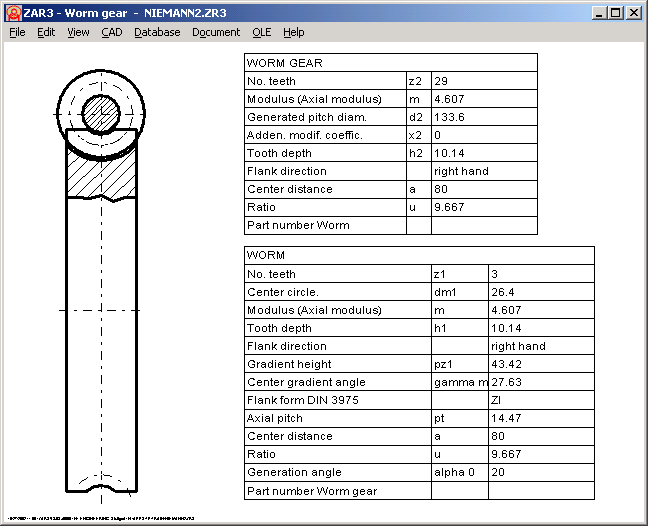
ZAR3 - Quick-View
New Quick View of ZAR3 shows drawing of worm gear together with tables of worm and worm wheel.
TR1 - Production Drawing and 3D-CAD
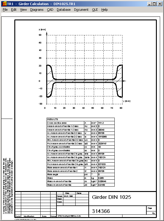
The girder software TR1 generates a drawing with profile geometry. And at "CAD" menu you can create a 3D drawing of the girder geometry.
WL1+ Production Drawing of Shaft Geometry
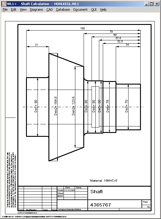
The shaft calculation program WL1+ generates a dimensioned production drawing of the shaft.
TOL2 - Insert and Delete Groups
When inserting or deleting groups, index of the items changes. This changes the element numbers defined at "Critical Distances". The new version re-indexes group numbers defined as critical distances after deleting or inserting groups.
Command-Line Mode and Batch Mode
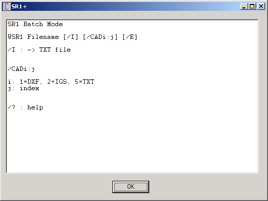
Now you can execute all HEXAGON programs in the background without GUI. Parameter for output of a text file with calculation results is /I or /i.
Example for bolted joint program:
WSR1.EXE C:\SR1\TRAIN\1_2001.SR1 /i
SR1 loads the .sr1 file, calculates the bolted joint, and writes results into a text file that could be loaded with Excel, for example. Name of the output file is the same as for input file, but with file extension txt.
Batch Mode for CAD Drawings
If you want to generate a drawing or diagram as DXF or IGES file, instead of a result table, use parameter "/CAD":
CAD-Format:Index/CAD
CAD-Format: 1=DXF, 2=IGES
Index: See CAD->Diagrams... or CAD->All..
Example:
WSR1.EXE C:\SR1\TRAIN\1_2001.SR1 /CAD1:13
generates production drawing as DXF file.
Problems with Novell Client
If you installed a network version with write-protected database directory under Windows 2000 and Novell Netware and Client 4.8, database access generates an error. Use Novell Client 4.7, and all is ok.
Problems with "." in Path names
Do not use dots for directories and file names. The only dot in a filename should be the one in front of the file extension.
CAD Drawing Element File
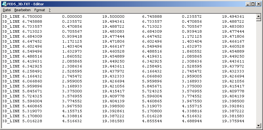
Output into a neutral text file has been added to the CAD formats DXF and IGES. This can be useful for import of geometry information into a CNC program or into Excel.
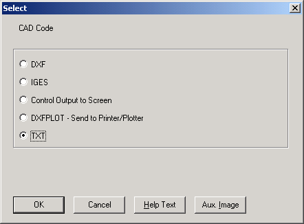
Example screen shows output of a 3D helix of a conical compression spring, generated with FED5. Drawing element: 3D-Line (x1, y1, z1, x2, y2, z2).
DXF - Digits Configuration
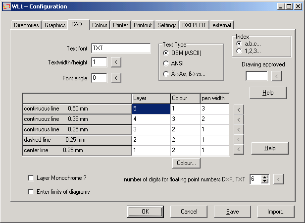
Number of digits in DXF files was fixed to 6 until now. Precision can be configured in the newer versions for DXF and TXT files.
CAD - Text Type configurable
In the new versions you can configure if special characters like German "öäüß" should be saved in format OEM or ANSI in DXF or IGES files. The third item replaces ÄÖÜ by Ae,Oe,Ue and ß by ss, ² by 2, ± by +/-, µ by u.
Linux Versions of HEXAGON-Software
Linux versions of all HEXAGON programs will be available soon.
Pricelist | Order | Update Order | E-Mail | Homepage