English
Deutsch
Info Letter No. 46 December 1997
Copyright by HEXAGON Software 1997
WL1+ Quick View
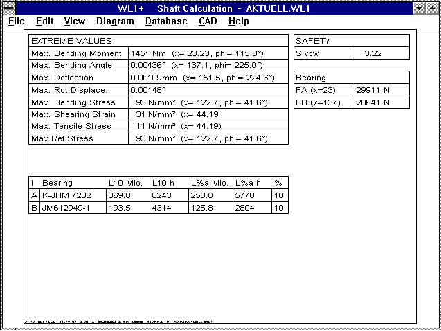
The life expectancy of roller bearings has been added to the
WL1+'s Quick Output.
WL1+ Safety Margin
Until now WL1+ has calculated the safety margins in relation to
alternating load due to bending, tension/pressure and torsion.
In the new version you can choose whether torque is alternating,
pulsating or resting.
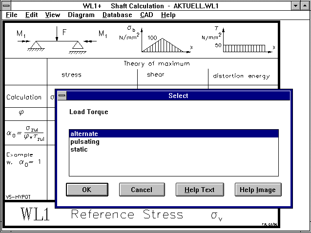 WL1+ calculates the reference stress in relation to Sigma bw.
The result is one value for the safety margin:
S = Sigma bw / Sigma v.
WL1+ Load Type
You can select whether the load should be alternating, pulsating
or static for torque and axial forces. Bending stress (from
shearing force, path load and bending moments) are always
alternating due to the rotating shaft, even when the load is
purely static. The load frequency is equal to the rotational
speed of the shaft.
With the help of the reference stress, the general state of
stress is converted to a plane stress. The safety margin is
calculated from:
S = sigma bw / Sigma v

Dependent on the strength theory:

Sigma v = SQRT ( sigma² + ( alpha0 * phi * tau )²)

The different stress states can be taken into account with the
correction value alpha0:

          Sigma bw
alpha0= ------------
          phi * tau

Whereby when tau occurs with alternating torque tau w is used;
for pulsating torque tau sch is used; and for static load tauf F
is used.  phi is dependent upon the strength theory (1, 2 or
1.73).

Example:  A shaft made of St50 is stressed by the bending moment
Mb and the torque Mt.  How great is the correction value ã0 in
accordance with the shear strain energy theory when:
a) bending occurs alternating, torsion resting;
b) both occur alternating;
c) bending occurs resting, torsion occurs alternating?

The limit stress can be taken from the WST1 material data base:
sigmabF=450N/mm² sigmabW=250N/mm²
tauF=180N/mm² tauW=150N/mm².

With phi=SQRT3

a) alpha0 = sigmabW/(phi tauF) = 250 / ( SQRT3 * 180 ) =  0.8
b) alpha0 = sigmabW/(phi tauW) = 250 / ( SQRT3 * 150 ) =  0.96 ÷ 1
c) alpha0 = sigmabW/(phi tauF) = 450 / ( SQRT3 * 150 ) =  1.7
The correction value ã0 is ascertained by WL1+ when a material is
selected from the data base and the strength values are known.
WL1+ Tension and Bending Stress
To allow for overloading of tension stress onto the reference
stress, the tension stress on the bending-alternating stress
portion of the reference stress is converted as follows:
sigmaz alternating: Sigma vb = Sigma b + Sigma z * Sigma bw / Sigma w
sigmaz pulsating: Sigma vb = Sigma b + Sigma z * Sigma bw / Sigma sch
sigmaz resting: Sigma vb = Sigma b + Sigma z * Sigma bw / Re
WL1+ Crit.Rotat.Speed for Triple Bearing
Now it is also possible to calculate the resonance speed for
bending vibrations for triple bearing shafts. Since this
drastically increases calculation time, it is possible to switch
off the calculation for bending critical rotational speed, under
"Edit->Calculation". The rotational speed for torsional fatigue
is independent of the number of bearing positions and can
therefore always be displayed.
FED8 - Spring Energy
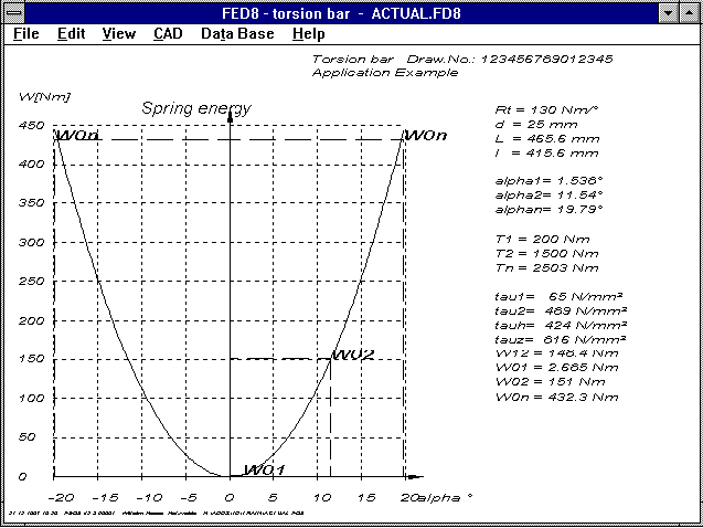 A diagram showing the curve for spring energy is now included
in the FED8 software for calculation of torsion bars. For
alternatingly loaded torsion bars, the displacement angle goes
from -alpha to +alpha. The maximum spring operation from -ãn to
+ãn is then Mn times ãn (Index n = usable displacement angle for
shearing stress tau n = tau perm).
FED2 - Index kn
For the extension spring calculation, the Index n is output as
usable spring path for static load, for which the shearing stress
tau n = tau zul. For dynamic load, the corrected shearing
stresses (tau k = tau * k) are used for tau k1 and tau k2. The
corrected shearing stresses tau k1 and tau k2 are used for
positions 1 and 2 in the printout, for Positions 0 and n the
values tau 0 and tau n are used. In the new version, tau kn =
tau n * k are also displayed, this makes it clearer why tau k2
can be greater than tau n.
======================================================================
Spring length   travel   mm   Spring force N      tau N/mm²       S
======================================================================
L0=  27.47ñ0.8                F0=    8.47         tau0 =   86
L1=  39.98      s1=  12.51    F1=   45.62ñ5.38    tauk1=  559     1.39
                sh=  10.00    Fh=   29.69         taukh=  364     1.09
L2=  49.98      s2=  22.51    F2=   75.31ñ5.83    tauk2=  923     0.84
Lkn= 45.96      skn= 18.49    Fkn=  63.38         taukn=  777     1.00
Ln=  50.41      sn=  22.94    Fn=   76.58         taun =  777     1.00
----------------------------------------------------------------------
                                                (S = tau zul. / tau y)

       Sigma perm./ Sigma q2 = 0.68       Sigma hperm./ Sigma bh = 0.67
FED2 - Pre-Stress Force
When only one spring length and matching spring force is
available, then F1=0, L1=L0 and sh=s2 are entered for the
pressure spring calculation. In the tension spring calculation
this is different because the pre-stress force with which the
coils lie over one another must first be overcome. This means
that during dimensioning and pre-dimensioning the pre-stress
force F0, must be entered for F1 and not F1=0.
10 Year Anniversary for HEXAGON Software
Although HEXAGON GmbH wasn't founded until 1990, we had already
developed our Tolerance Program TOL1 in 1987. Parallel to the
Further Informatic Degree, our Engineer Office Ruoss, was
already writing software for mechanical engineering designers for
use on 8086-PCs with 4,77 MHz and 256 kB memory, with 360 kB disk
drives without hard drives. At the time this was highly advanced
compared to the previous computers such as the Sinclair ZX81 with
only 1 kB of memory! The development tool Turbo Pascal 3.0 was
contained in a 40 kB file (TURBO.COM) which included the compiler
and program editor. This meant that a 360 kB disk included the
development tool, the source code and finished program! In
comparison: Borland Delphi 3.0, the successor to Turbo Pascal
requires 100 MB memory on the hard drive, this is an increase by
a factor 2500! After our Tolerance Program, TOL1 followed the
toothing program ZAR1 and the pressure spring program FED1. The
highlight in our programs was the introduction of graphic
representation of the tooth form in ZAR1, and the spring drawing
in FED1, later followed the feature for output to DXF or IGES
files via the CAD interface. At the time, a CAD interface for
calculation programs was something new, and was only available
with HEXAGON software. At the time, most users stated that they
rarely used the CAD interface, today, this is a standard part of
any calculation program. For data bases with material values and
DIN parts, the "old" DBF format from dBase 3+ is used. This
means that the files can be editted and worked on with any data
base or spreadsheet program (dBase, Access, FoxPro, Excel,
Quattro Pro, StarOffice). After our Tolerance program, Toothing
program and Pressure Spring program followed both of the graphic
conversion programs, HPGL Manager and DXF Manager. Both of which
were and still are useful for internal program development
(generation of source code for DXF drawings). Then followed the
programs for tension and spiral spring calculation, shaft
calculation, bolted joints, pressed fits and shaft-hub joints.
Along side this, we continually improved and updated our user
interfaces.
Since 1992 we have been able to offer a UNIX version of the HPGL
Manager and ZARXE, for DEC and SUN work stations. Although Unix
version were sought after in 1990-92, this has now dropped off so
that no further development in the Unix area is carried on. Much
more successful has been the conversion to Windows. The first
HEXAGON Windows version was the HPGL Manager, available in
June 1993. All programs were converted after this to Windows.
Today, 95% of our orders are for Windows versions.
In 1997 we brought out new programs, FED8 for calculation of
torsion bars, and TR1 for girder calculation. New and future
oriented in all of our programs is the feature, as an alternative
to printing out on a printer, the possibility for creating HTML
files which can be read by Netscape or Internet Explorer.
WN2 - Dedendum
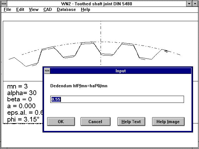 The tooth dedendum, hfP, or tool addendum haP0, wer until now set
a 0.55*m. According to DIN 5480 this is the factor for
broach toothing manufacture. However, a factor of 0.6*m is
recommended for hobbing manufacture, and a factor of 0.65*m is
recommended for wälzstossen. With the new WN2 version you can
enter the dedendum factor freely. I would like to thank Mr
Canovas of Moog, Böblingen, Germany for pointing this out.
FED1+ Quick View
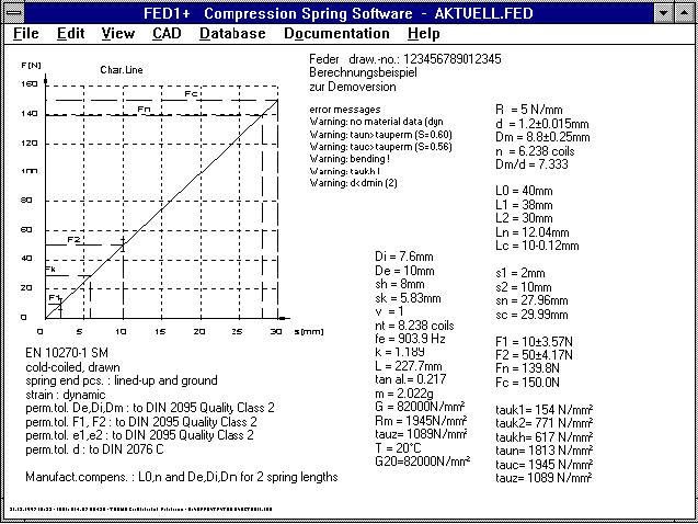
The output for the manufacturing adjustment has been moved down
one line. This avoids the text in the second column being
written over.
FED3+ Clamping Angle
With twists springs, the clamping angle delta is in the opposite
direction to the spring angle alpah. This is often
misunderstood, and was displayed falsely in the auxiliary picture
for the application example.
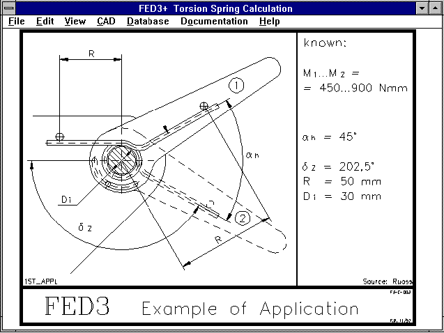 Analogue to pressure spring with
L = L0 - s
applies to the torsion spring
delta = delta0 - alpha
FED3+ Clamping
The program allows you so choose between fixed clamping
and supported spiral. For supported spiral, the lever arm for
the center axis must also be entered. The program then
calculates the deflection of the spiral and the resulting
additional angle displacement ß. For fixed clamped spirals the
spring is held directly on the outer diameter. When the spring
ends are bent axially or inwards, you should also select "fixed
clamping". A new auxiliary picture is provided for clamping.
Windows Versions for NT
All Windows version since 1996 can be installed without problem
under Windows NT. The only limitation is that you can still only
use the 8.3 format for file names. This means 8 characters for
the file name, and three characters for the extension.
Don't use blanks in file names!
Please don't use blanks in file names. Although Windows 95/NT
and old DOS versions allow this. This can result in your not
being able to load files when changing to a newer version. If
this has already happened, install the old DOS version again,
load all your files with blanks in the file name and rename and
save them under new names.
Seminar Schedule 1998
We are offering the following seminars in 1998: toothing and
gearing calculation, spring calculation, working design
calculation and DIN ISO 9001 certification. If you are interested
in taking part in one of our seminars, please contact us to
obtain our Seminar Schedule. We now offer a seminar on "Vibration
Activation and Noise Behaviour in Gears". This seminar, of ever
increasing importance for minimizing gear noise, is held by Dr.
Müller.
Seminar: Vibration and Noise Behaviour in Gears
This seminar is a sensible follow-on, providing the newest
information about noise and toothing, and noise behaviour in
gears, and provides important information on preventing noise
development during gearing pre-dimensioning. The topics covered
are listed below:
Basic knowledge in vibration activation and vibration behaviour
Dynamic behaviour of toothing gears; determination of datum
rotational speed N, as well as dynamic factor Kv.
Vibration behaviour of the whole gear: Influence of the whole
system "gear" including drive and work machines, also accounting
for shaft bending.
Measures for influencing the vibration and noise activation by
spur gears; toothing geometry, toothing deviation and toothing
adjustment, tooth flank play, etc.
Influence parameters for bevel gears
Special occurence of vibration: Getriebeasseln
Relationship between noise activation and noise radiation of
gears.
Measures for influencing solid borne noise conduction and noise
radiation: Housing design.
Selected question about measuring technology
Homepage


