 | English
| Deutsch
| English
| Deutsch
FED Material Database: SWOSC-V and SWOSC-VHV
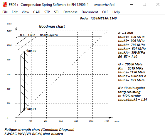
The oil tempered spring steel wires SWOSC-V according to the Japanese JIS standard and SWOSC-VHV are comparable with VD-SiCr and VD-SiCrV according to EN 10270-2. The two materials were added to fedwst.dbf, the technical data was taken from Suzuki-Garphyttan and is similar to Oteva70 and Oteva75.
FED Material Database: Nivaflex 45/18

Nivaflex 45/18 is a "watchmaker's wire" made of 45% cobalt, 21% nickel, 18% chromium, 5% iron, 4% tungsten, 4% molybdenum and 1% titanium, preferably for micro springs between 0.2 and 0.5 mm in diameter. Fatigue strength values are not available, tensile strength values hardened, 2h 550°C. There was already a similar material in the material database, Nivaflex 45/5, with slightly higher strength and fatigue strength data. The only difference to Nivaflex 45/18 in the chemical composition is that Nivaflex 45/5 in addition to 45% cobalt, 21% nickel, 18% chromium, 5% iron, 4% tungsten, 4% molybdenum and 1% titanium still contains 0.2% beryllium.
FED Material Database: UGI 202N
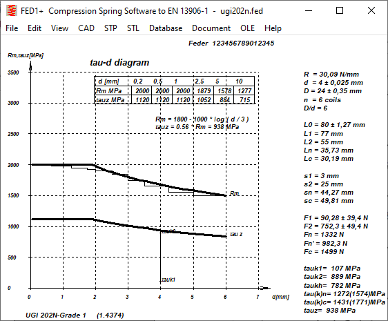
UGI 202N is an austenitic stainless, non-magnetic steel with a high manganese content (X8CrMnNiN18-9-5) and has been added to the materials database. Fatigue strength values are not available.
FED Material Database: EN 10270-3 is ISO 6931-1
EN 10270-3 was withdrawn years ago and replaced by ISO 6931-1 (see Info Letter 184). If you don't know that, you will search in vain for stainless spring steels according to EN 10270-3 in the spring database. Therefore, "(EN10270-3)" is now listed under NAME4.
FED3+: Spring drawing without Dimensions
The leg length of bent legs is not clearly defined, neither in the FED3+ drawing nor in EN 13906-3. For this reason, the torsion springs are now displayed without dimensions. Only if you change the setting under "Edit\Calculation method" will the legs be drawn with dimensions as before.
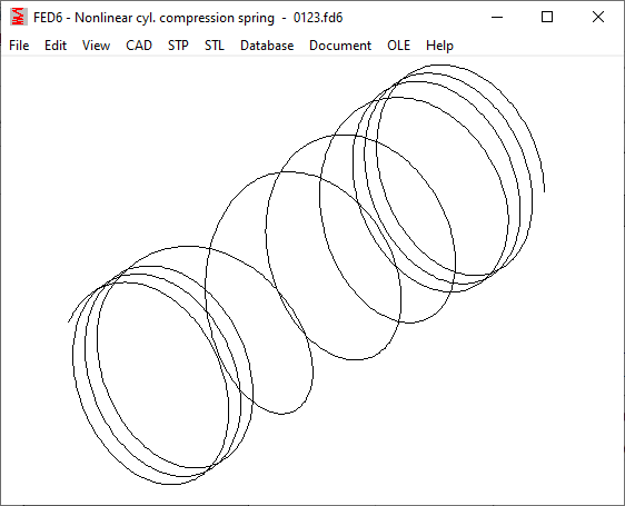
Just like in FED1+, FED3+, FED5, FED17, you can now also export the center line of the spring as a 3D helix in STP format in FED6 and FED7 and transfer it to CAD. To represent a 3D spring, you can then extrude the wire around the helix in the CAD program and cut off the spring ends (in the case of ground spring ends).
FED3+: Improvements in Pre-Dimensioning and Dimensioning
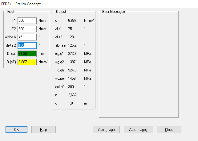
In the pre-design or in the design basic data or in the design quick input, the entered spring angle delta2 was changed for the calculation method R = 1/(1/R0+1/RS1+1/RS2) and for supported springs with bent legs and a large lever arm. Now only the coil diameter is adjusted when changing the input data.
FED14: Application static/dynamic saved
Input of application static/dynamic saved and loaded in f14 file.
ZAR1+: Dimensioning of Multi-Stage Gears
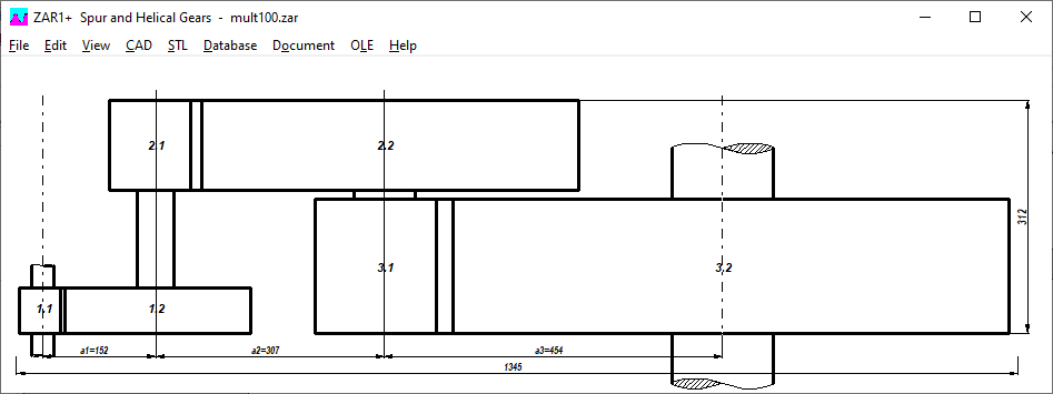
When pre-designing multi-stage gears, the most important dimensions have been added to the drawing: center distances between the stages, overall length, overall width.
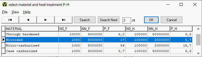
ZAR5, ZAR7, ZAR8: Load Spectrum: Material and Heat Treatment separated to Gear Pairs
So far, the selection of the material type for load collectives in planetary gears applied to both the sun-planet gear pair and the planet-ring gear pair. Now you can choose different fatigue parameters for pairing S-P and P-H. There are different values for the application factors KAH and KAF calculated from the load spectrum because the number of load cycles is included in the calculation. So there are now 4 different application factors in ZAR5: KAF-SP, KAH-SP, KAF-PH, KAH-PH. In ZAR7 for plus planetary gears there are 6 and in ZAR8 for Ravigneuax gears there are even 8 different application factors (for 4 gear pairs Si-Pi, Pi-Pe, Pe-H, Pe-Se).
ZAR1+,ZAR3+,ZAR5,ZAR7,ZAR8,ZAR9: 3D Printing of Helical Gear Wheels and Worms
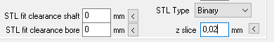
Spur gears can be made quite easily with the 3D printer from the STL files from the ZAR program. It doesn't look so nice with helical gears and worms, the sloping plane is stepped. Step height is the layer thickness in 3D printing. The layer thickness can be changed under "File\Settings\CAD" (z slice). Default is 0.1mm, reduce this to the minimum possible layer height setting of your 3D printer to get a more smooth tooth surface.