 | English
| Deutsch
FED1+,2+,3+,17: Haigh Diagram

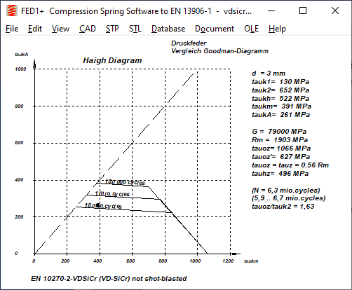
In addition to the modified Haigh-Goodman diagram, there is now also a "real" Haigh diagram, even if this is not really relevant for helical compression springs.
Smith chart and Haigh chart are for alternating and pulsating loads, the mean stress taukm is plotted on the x-axis and the stress amplitude taukA is plotted on the y-axis.
Goodman diagram and Haigh-Goodman diagram are only for pulsating loads, the x-axis shows the prestress tauk1 and the y-axis shows the lifting stress taukh.
The calculation of helical compression springs according to EN 13906 and HEXAGON FED only considers pulsating loads (if the load changes, a firmly clamped spring would switch between compression and tension). Therefore the left side of the Haigh diagram is blank here.
This Haigh diagram is used in a research project by the Association of the German Spring Industry to determine new fatigue strength values at the TU Ilmenau, so you can compare the Haigh diagrams used there with those in HEXAGON FED.
The spring length L1 for the preloaded spring is usually fixed, while the stroke (sh=L2-L1) can be constant or variable. An average spring length Lm with an average shear stress taukm is rather impractical for helical compression springs. These stresses used in Smith and Haigh diagrams are easy to convert:
mean stress taukm = (tauk2+tauk1)/2
Stress amplitude taukA = (tauk2-tauk1)/2 = tauh/2
In the case of non-linear compression springs, the mean stress relates to the mean spring force, but not to the mean spring length or half the stroke.
FED1+,2+,3+,5,6,7,17 Tip: Goodman Diagram Setting tauoz = tauz

Theoretically, the upper horizontal line in the Goodman diagram should be the allowable (static) shear stress tauz because the allowable deflection=0 here. In fact, this value is usually lower in the Goodman diagrams in EN 13906-1. But you can set "tauoz=tauz" under "Edit\Calculation method", then the upper stress in the Goodman diagram is the permissible shear stress tauz.
The newly determined Goodman diagrams for DH and VDSiCr from the research project IGF 19693 BR by VDFI and TU Ilmenau are usually fairly close in this setting.
Comparison of Goodman diagrams EN 13906-1 and research project IGF 19693 BR
In EN 13906-1 there are Goodman diagrams of DH according to EN 10270-1, TD according to EN 10270-2, VD according to EN10270-2, 1.4310 according to EN 10270-3, 1.4568 according to EN 10270-3.
The research project examines: FDSiCr, VDSiCr, VDSiCrV, DH, 1.4310, 1.4568. TD and VD are not examined. Strange that FDSiCr is tested for fatigue strength, although according to EN 10270 this material is only intended for static applications. According to the determined, almost identical fatigue strength diagrams from IGF 19693, FDSiCr and VDSiCr are equally suitable for dynamic stress. But that may be coincidence, the only difference between FD and VD wires might be that VD is tested for surface cracks to keep the risk of crack formation and crack propagation to fatigue failure low.
It is also strange that the newly determined Goodman diagrams of VDSiCr are compared with the old ones of VD (without SiCr). However, the newly determined Goodman diagrams for VDSiCr from 2021 are comparable and almost identical to those from the Bosch Kraftfahrtechnisches Taschenbuch from 1995, which are used in HEXAGON FED.


The fatigue strengths (N=1E7) of VDSiCr from HEXAGON FED (with the setting tauoz=tauz) are almost identical to the newly determined IGF data, both shot-peened and unpeened. However, there are clear differences in the fatigue strength (N=1E6), which means that the calculated service life for overstressed springs is significantly lower.


DH: In the case of unblasted spring steel wire DH, the permissible lifting stress for tauk1=0 is somewhat lower, but greater for higher preload than according to EN 13906. Shot peening increases the permissible lifting stress by almost 100%. According to EN 13906, on the other hand, by only 20 to 25%. Thus, for DH, the permissible lifting stress for shot-peened springs is more than 50% higher than according to EN 13906.


1.4310: In the case of spring steel wire 1.4310, it is not mentioned whether the type 1.4310-NS or 1.4310-HS was examined. Because the allowable shear stress (upper horizontal) in the Goodman diagram is so low, it can only be NS. For d=3mm one can read tauzul= 770 MPa. However, the permissible shear stress (tauzul=0.56Rm) at d=3mm is for ISO 6931-1-4310-NS = 868 .. 1002 MPa,
and for 4310-HS even 952 .. 1098 MPa. The permissible shear stress in the new Goodman diagram is therefore even worse than for 1.4310-NS. The permissible lifting stresses for springs that are not shot-peened are lower for tauk1=0 than according to EN 13906- (320 instead of 380 MPa for d=3mm) and higher from tauk1=300MPa. For shot-peened springs, on the other hand, the newly determined permissible shear stresses are all higher than before.


FED: fatigue strength (1E7 cycles), fatigue strength (1E6 cycles), service life
The comparison of the fatigue strength diagram for 10 million load cycles and the fatigue strength diagram for 1 million load cycles according to IGF differs significantly from the Goodman diagrams from EN 13906. While the permissible stress amplitude according to EN 13906-1 for 1E6 load cycles was approx. 25% higher than for 1E7, according to the new Goodman diagrams it is only between 10 and 15%. Conversely, for the calculation of the number of load cycles and service life, this means that these become significantly lower if the permissible fatigue variation of stress is exceeded. It is therefore planned to add a field 1E6_1E7 to the spring material database fedwst.dbf, in which the quotient tauhzul,1E6 / tauhzul,1E7 can be entered.

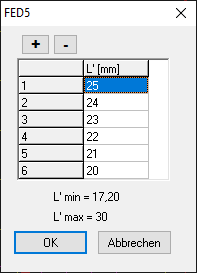
FED5, FED6, FED7: List up to 6 additional spring positions

Similar to FED1+, you can now also enter additional spring lengths in FED5 and FED6 and FED7, for which the spring force is drawn in an additional spring characteristic curve (View\Spring characteristic\F'-s').

FED1+,2+,6: Coil ratio Dm/d added
Coil ratio w = Dm/d has been added in Quick3 and Quick4 View.
SR1/SR1+: Split clamping plates with chamfers or countersunk


If a countersink or chamfer is to be taken into account for the calculation of surface pressure and elastic compliance, the clamp piece with countersink or chamfer is made into two cylindrical clamping plates: one with a countersink and one without. Or even three plates are created from one clamping plate if chamfers or countersinks are to be taken into account on both sides. Starting from a 45° chamfer, there is a new clamping plate with the height of the chamfer, the old clamping plate is reduced by the same height. With a 45° chamfer on the bore diameter, Di increases by 2 x chamfer height, with a 45° chamfer on the outside diameter, De decreases by 2 x chamfer height. This is now also possible automatically under "Edit\Clamping plates" "Chamfer, countersink".

This splitting of the clamping parts is disadvantageous when calculating the amount of setting fz, because the new clamping plates have no separating surfaces. Therefore, you can now enter the number of real clamping plates under Edit\Load. This input is temporary and is only used to calculate the setting amount fz.

SR1/SR1+: pressure database (pressung dbf)
The German and English versions of the pressung.dbf database with material data for the clamping plates differ and are not interchangeable. Please note if you use the German and English versions. In the English version, an error has now been found in the modulus of elasticity of the material "SF Cu F24", this must be 123000 MPa, not 12300. Please correct under "Database\Material Plates\Nut\Base data 0 (pressung.dbf)" .
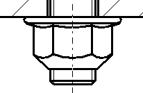
SR1/SR1+ Tip: Input tightening torque of friction nuts
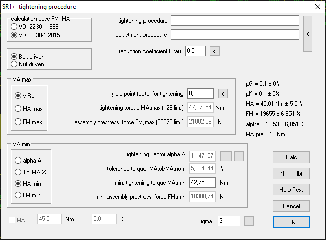
When using self-locking nuts with MApre friction torque, entering torque tolerances is unfortunately not as easy as with normal nuts.

For self-locking nuts with friction torque, the yield strength factor nueRp must be entered; MA,max and MA +/- % cannot be entered here. In this case, nueRp can be changed until the desired tightening torque MA,max is displayed in the background.

Tip: Save settings in cfg file
Settings are saved in a cfg file (e.g. fed1.cfg). A cfg file is created when you click "Save" button under "File\Settings". For network versions, the network drives are configured under "File\Settings\Directories". The temporary drive should be local, e.g. "c:\temp". It is advisable to create a sample cfg file, which each user then copies to their local hard drive. Best in "c:\hexagon".