 | English
| Deutsch
WN2/WN2+: New result graphics at Quick Input added

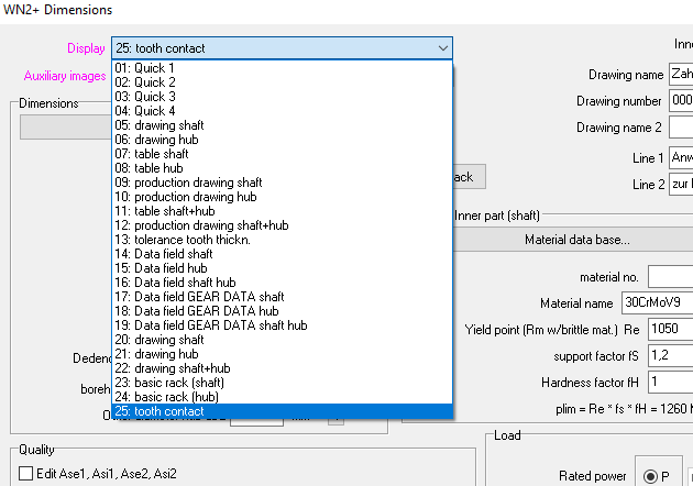
In the Quick Input, 5 additional result graphics can be selected under "Display": shaft drawing, hub drawing, shaft reference profile, hub reference profile, meshing. The result graphics displayed in the background window are updated with the "Calc" button.
WN2 /WN2+: Fillet root side fit, not for major diameter fit nor minor diameter fit
Splines according to DIN 5480 are usually flank-centred. However, DIN 5480 also allows the exceptional case that the spline is centered on the outside diameter or inside diameter. DIN recommendation: Due to the increased manufacturing effort, diameter-centric splines should be limited to exceptional cases. In this case, the flank fit must be given a lot of backlash (9H/9c) to avoid overdetermined centering. And the teeth must be designed with tip chamfer (>=0.1*m) because of the root fillet radius of the opposing tooth. As a result, only a small load-bearing fitting surface remains on the tooth tip. In order to increase the bearing surface, DIN 5480 recommends multiple teeth for divisible numbers of teeth.
In WN2 you can only calculate flank-centered splines. Multiple teeth with divisible numbers of teeth are a special case, this is not possible with WN2+.
Questions also remain unanswered for spline fits centered on the inside diameter. H7 / h6 is recommended for the inner diameter tolerances, but there is no information on the inner diameter itself. For example
"DIN 5480 - I 120 x 3 x 38 xH7 h6 x 9H 9e" the reference diameter 120 is probably the outer diameter of the shaft. The more important reference inner diameter here would be 114 mm.
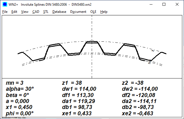
In WN2+ you could calculate and use the tooth height factors for outside and inside diameter centering for a tooth contact graphic (but without chamfer).
Outside diameter centering:
ha/mn = dB/(2*m) - z/2 - xe
Because of the flank tolerances, the mean generation addendum modification factors must be used here:
       PROFILE SHIFT COEFFICIENTS
       ----------------------------------------------------------------------
       Profile shift coeff.              x               0,45000    -0,45000
       ----------------------------------------------------------------------
       Profile shift                     x mn     mm       1,350     -1,350
       ----------------------------------------------------------------------
       Gen.addend.modif.coef. max.eff.   xemax           0,44192    -0,45000
       ----------------------------------------------------------------------
       Gen.addend.modif.coef. max.act.   xemaxE          0,43528    -0,45981
       ----------------------------------------------------------------------
       Gen.addend.modif.coef. min.act.   xemin           0,42373    -0,47598
       ----------------------------------------------------------------------

xe1 = (xe1maxE+xe1min)/2 = (0.43528+0.42373)/2 = 0.4295
xe2 = (xe2maxE+xe2min)/2 = (-0.4581-0.47598)/2 = -0.46704
ha1/mn = dB/(2*m) – z/2 – x1 = 120/(2*3)-38/2-0.4295 = 0.5705
hf2/mn = dB/(2*m) – z/2 – x1 = 120/(2*3)-38/2+0.467 = 0.533
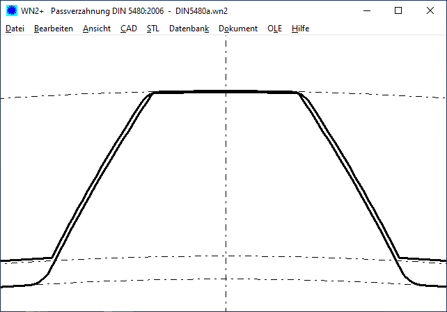
In the tooth contact graphic you can see the collision of the tooth tip of the shaft profile without tip chamfer with the root fillet radius of the hub profile.
Conclusion: Unfortunately, the DIN 5480 special cases of splines with major diameter fit or minor diameter fit cannot be calculated with WN2 or WN2+.
WN2/WN2+: ISO tolerance table H11/h11 in production drawing

Since version 11.1.2, a fit table with nominal / maximum / minimum dimensions is displayed in the production drawing (only shaft or only hub, not both), in addition to the dimension H11/h11 at the lower edge of the drawing. Unfortunately, the dimensions in this table were incorrect, this has been corrected. Please check the ISO table in the manufacturing drawing. If you encounter the error, you can request a free update from us.
WN4, WN5: Production drawing improvements
In WN4, the dimensioning of dri and di was reversed in the hub drawing. In WN4 and WN5, some dimensions were written beyond the edge, these are now displayed reduced in the next larger standard scale. And at text printout, an eventually entered hub outside diameter was not printed.
With WN5, the form diameter of the hub DFI according to ISO 4156 is output independently of the flank tolerances of the external spline profile.
TR1, GEO1+, GEO2, ZAR4: Import DXF file with LWPOLYLINE (AcDbPolyline)
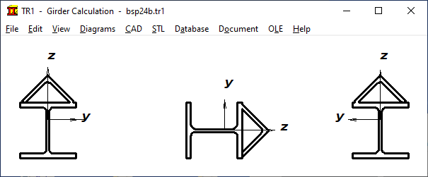
Profiles can be taken from DXF file if they are defined as a continuous polyline. Only then can the program automatically calculate the area, area moment of inertia, center of gravity and section modulus. The DXF drawing elements POLYLINE with VERTEX and LWPOLYLINE with AcDbPolyline are available for this. The DXF import with LWPOLYLINE has been improved, in some cases or with some CAD systems not all drawing elements were correctly imported.
DI1 (O Ring software): Help buttons to select ISO tolerances
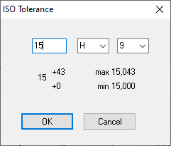
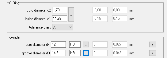
ISO tolerance fields are displayed for selection with the ".." buttons when entering tolerances. For inner seal, lower case letters were displayed for shaft tolerances instead of upper case letters for bore tolerances, this has been corrected. You can also enter the ISO tolerance field directly, DI1 then calculates the maximum and minimum dimensions.
SR1 / SR1+: Show safety margins above 1000 ?
Safety numbers above 1000 have not been given so far because they are negligible and overflow tables. The associated stress in MPa is then usually rounded to 0. In the future, safety margins > 1000 will be printed in the text printout (not in the Quick views).
       FACTORS OF SAFETY
       ======================================================================
       Safety against loosening          FMzul/FMmax,req          1,21
       ----------------------------------------------------------------------
       Safety yield point red.B          SF=Re/Sig.redB           1,16
       ----------------------------------------------------------------------
       Safety ag.fatigue fract.(centr.)  SD=Sig.AS/Sig.a       2128,81
       ----------------------------------------------------------------------
       Safety plate surface pressure     Sp=pG/pmax               0,91
       ----------------------------------------------------------------------
       Safety against slipping due to FQ SG=FKRmin/FKQreq         0,82
       ----------------------------------------------------------------------
       Safety against shearing           SA=Atau*tauB/FQ         12,23
       ----------------------------------------------------------------------
       Safety bolt bearing stress        SL=h*d*Re/FQ             0,96
       ----------------------------------------------------------------------
       Thread strip safety at Rm,max     m tr/m min.              1,29
       ----------------------------------------------------------------------
       Safety creep FV min               SKr=pGKr/pmaxKr          1,74
       ----------------------------------------------------------------------