 | English
| Deutsch
ZM3: New Software for Synchronous Belt Drives

There are many different profile shapes for synchronous belts. These have been summarized and standardized in ISO 17396 (T and AT profile, 2017) and ISO 13050 (profile G, H, R, S) from 2014. Before that, every belt manufacturer had its own standards and designations. Unfortunately, only the dimensions have been standardized. For the calculation of load and strength, each provider continues to use its own standards. There are a multitude of different factors, tables, diagrams and graphs. For synchronous belts made of rubber, polyurethane or neoprene, with tension cords made of steel, fiberglass, carbon, kevlar.
In ZM3, the strength is therefore only approximately calculated using the following data:
1. Tensile force and tension of the toothed belt
2. Surface pressure on the tooth flanks
3. Shear stress on the tooth
In ZM3 we use a breaking force FB similar to that of chain drives. In the case of synchronous belts, this depends on the incorporated tension cords (made of steel, fiberglass, carbon). As a default for FB, we use FB = 50 * (hs-ht) * b, which corresponds to an average tension of 50 MPa in the belt cross-section. If the proportion of tensile cords in the cross section is 20%, this corresponds to a tensile stress of 250 MPa.
The load-bearing portion of the remaining belt cross-section made of PU or neoprene can be neglected, if only because of the different elongation. The elongation of steel = sigma / modulus of elasticity is 0.12% at 250 MPa (for tensile cord made of glass fiber or carbon approx. 0.35% at 250 MPa)
Then a check of the permissible surface pressure on the tooth flanks. The surface pressure depends on the load (torque), application factor, height and width of the teeth and the number of teeth in mesh. The permissible surface pressure of the tooth flanks depends on the material and shape of the synchronous belt.
And finally, a shear stress for shearing off the teeth on the synchronous belt. As with the surface pressure, it depends on the load, the application factor, the number of teeth in mesh, the tooth width and the face width.
In ZM3, all tooth profiles are converted into a trapezoidal profile with transition radii.
Trapezoidal profile fits exactly for inch profiles X, L, H and metric profiles T and AT.


An H-profile according to ISO 13050 can also be constructed quite precisely in this way, even if a trapezoidal profile is no longer recognizable due to the large radii.

Profiles G, R and S according to ISO 13050 have involute flanks, the construction is complex.


In ZM3 these profiles are only shown imprecisely as a trapezoidal profile.
ZM3 also generates an image of the meshing of the synchronous belt with the pulley. With the T-profile it is noticeable that the backlash is very large. The T-profile should not be used for drives with reversal of the direction of rotation, unless the tooth profile of the pulley is changed.

With the AT profile, on the other hand, the teeth of the toothed belt are literally pressed into the tooth gap of the pulley. Wide teeth on the toothed belt and thin teeth on the pulley reduce the shear stress on the toothed belt.

In ZM3 you can generate the tooth profile of synchronous belt pulleys with trapezoidal profile as true-scale DXF file. Or generate an STL file straight away and create a 3D model of the pulley on a 3D printer. For variations, you can change the most important parameters for the tooth profile.


For profiles according to ISO 5296, ISO 17396 profile T and ISO 13050 profile S, the outer tooth width "br" is specified. For profiles according to ISO 17396 profile AT and ISO 13050 profile H, the inner tooth width "bh" is specified. For profiles according to ISO 13050 profile G and R, both tooth width "bh" and tooth width "bh" are specified (but they have different names), the tooth angle is calculated. ZM3 converts br and bh, the designation "bre" is the tooth width on the tangent to the outer diameter d0.
ZM3 is available now at a price of 224 euros for a single user license.
FED5: shear stress distribution diagram tau-x reversed

In FED5, FED6 and FED7 you can display the course of the tension along the spring body as a diagram, and that for every spring length between L0 and Lc. The x-axis is then the compressed spring body from 0 to the specified spring length. Which side corresponds to which side was not displayed, which is why a conical spring calculated with FED7 was shown reversed compared to the spring calculated with FED5. Therefore, the tau-x diagram in FED5 has been reversed, and the mean coil diameter of the spring ends is given in brackets.
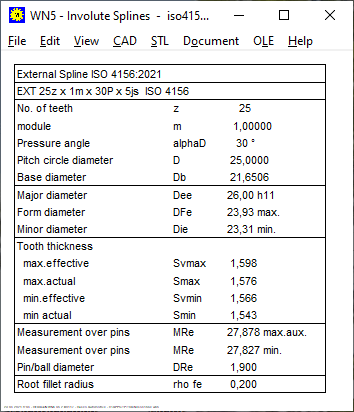
WN5: Table to ISO 4156 and ANSI B92.2M: WN5 V5.1 Bugfixed


New in WN5 V5.1 was a Quick4 view in the A3 drawing frame. Unfortunately, since this change, the old ANSI B92.2M table had been displayed in the manufacturing drawing even though ISO 4156 was selected. And the greatest dimension of the tooth thickness "Max effective" of the splined shaft was always displayed for H / h, even if H / d, H / e, H / f was selected. In the Quick3 and Quick4 view, however, the correct table was displayed. Affected customers with WN5 V5.1 will receive a free update, they have already been informed.
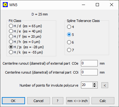
WN5: Fit Class H/js and H/k

In the latest ISO 4156: 2021 (also already in ISO 4156: 2005) there are not only the clearance fits H / d, H / e, H / f and H / h but also the transition fits H7 / js and H / k for a tight fit, in WN5 since V4.9. When calculating the dimensions of "js" and "k" for esv (fundamental deviation), the ISO dimensions according to the fit table do not apply, but rather the clauses "esv = (T + lambda) / 2" for "js" and "esv = (T + lambda) "for" k ". In the last version 5.1 of WN5, the dimensions according to ISO 286 were used. The pairings H / js and H / k are now significantly tighter.
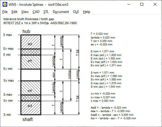
WN5: Tolerance Graphic: E nom, S nom, c max added
The nominal value of the tooth width and gap width Snom and Enom is the pitch P = m * pi / 2.
In addition, the largest possible clearance of a single tooth cmax has been added.

cmax = Emax-Smin = cvmax+2*lambda = cvmin+2*Ttot
ZAR4, GEO4: 2nd order Ellipse added

A 2nd order ellipse can be described very easily:
r = 2 * a * b / ((a-b) - (a-b) * cos (2 * phi))
When used as a non-circular gear, the second-order ellipse has the advantage that the gear and mating gear can have the same contour. To do this, the number of teeth must be divisible by 4 because the meshing is offset by 90 °. In the case of a "correct" ellipse, the contour of the mating gear must be calculated, the pitch curves of the elliptical non-circular gear and mating gear are different.

In ZAR4 and GEO4, as alternative to an ellipse, you can now select a second-order ellipse as pitch curve (ZAR4) or as a cam shape (GEO4).
ZAR4: Tooth contact drawings

Use the arrow keys to move the non-circular gear through the specified angle. The step angle delta phi can now be entered. Previously it was set to 180 ° / z1.
ZAR4: Calculate pitch curve from pitch angles of driving gear and driven gear

As a new option for the pitch curve, you can now enter the angle of the drive gear and the corresponding angle of the driven gear. To do this, enter the angle phi1 in 1 ° steps or less and the associated angle phi2 of the mating gear phi2. ZAR4 then calculates the pitch curves of gear 1 and gear 2:
r1 = a0 / (1 + dphi1 / dphi2) or r2 = a0 / (1 + dphi2 / dphi1)
Where dphi is the angle difference dphi1 = phi1 (i + 1) - phi1 (i)
WN2: Radial Runout Fr

In the table DIN5480: 1991 the permissible radial runout deviation of the hub under "Additional information Fr" was not correct. The radial runout of the internal and external gears are the same, but the runout of the hub was specified too small. Fr has been corrected.
In the new table DIN5480: 2006, however, no concentricity deviation Fr is given.
SR1 Quick Input: Additional text (line 4)

If the 3 lines of text are not enough for you, you can now write a fourth line (max. 100 characters). The 4th line is output in the table drawing and the quick views, but not in the text printout.
SR1 Quick Input: take over the clamping plate data from the previous element

With the "<+" button, the data of the previous plate are adopted for the next clamping plate. Only the material had to be selected again from the database in order to take over the material data. In future, the material data will also be adopted.
Reverse the SR1 clamping plate assembly
If you swap screw and nut, you also have to reverse the arrangement of the clamping plates. There is now a new button "<^>" in the quick input.
SR1 Quick3,4, table drawing: clamping length ratio Lk / d

The clamping length ratio Lk / d is added to the views.
SR1: M1.4 screw
Thread M1.4 has been added to the database, plus a hexagon socket screw M1.4 according to DIN 912 and nut 1.4 DIN 934
SR1 Tip: bolted joint with stud bolts
It is often asked how one can calculate a stud bolt with nut. If the thread screwed in first does not have to be calculated, that's easy: The screwed-in bolt is defined as a bolt with a large special head.
If the stripping safety of both thread sides is to be calculated, 2 calculations must be carried out:
1. bolt as a screwed-in threaded bolt with a large special head as DSV

2. bolt with nut-screw head as ESV

The nut is then defined as a screw head and the arrangement of the clamping plates must be reversed for this. To automate this, there is a new button "<^>". The assembly preload FM, max (FMzul according to VDI 2230) must be taken over from the first calculation.
SR1 Tip: Calculate clamping plates with a large bore or elongated hole

If the bore of a clamping plate is larger than the bearing diameter dw of the screw head or nut, the screw connection according to VDI 2230 cannot be calculated. Fatal error, calculation not possible. Even thick washers or sleeves are of no use. According to VDI 2230, only the change in length of the clamping plates due to tension and pressure is calculated, but not the bending and curvature of washers and sleeves. The only thing that helps is to enlarge the head of the screw and nut: use flange screws and flange nuts.
Fit text into tables and diagrams

The text size on the graphics screen does not change continuously according to the window size and resolution, but in steps. Therefore it can happen that text in tables is displayed too big or too small. This can be adjusted under File \ Settings \ Graphics: Change text height factor or text width factor, the standard setting is 1 for the text height factor and 0.8 for the text width coefficient.

Old HEXAGON Software running on new hardware and new operating system
Some of our customers are still using 20-year-old versions with new hardware and a new PC. Most of them run without any problems, although the current operating systems at that time were called Windows 95, Windows 98 and Windows 2000. And a hard drive partition couldn't be larger than 2 GB. Older versions sometimes cause problems with database access if the storage space is larger than 2 TB (2000 GB). In 2006 and 2015 the database problems with the old and new database module were fixed.
1 Year Corona
If you look back today on the first corona wave in the first half of 2020, the numbers in Germany look harmless compared to today: fewer than 200,000 infected people, 9,000 deaths, and the highest 7-day incidence was 45. When shops and schools were closed and airports in March 2020, the 7-day incidence was just 10. In the second wave from September 2020 to February 2021, 2 million infected people, 60,000 deaths, the highest incidence over 200. The second wave was triggered by people returning from vacation. This will probably be repeated in 2021, when there will be the fourth wave. The third wave began in March 2021, triggered by international mutations of the virus. Corona will probably be with us for a long time. The vaccine manufacturers are counting on the fact that their products will be needed for a long time due to their diminishing effectiveness and new mutations.
EU President in the Corona shopping frenzy
Von der Leyen is negotiating with Biontech-Pfizer about the delivery of a further 1.8 billion vaccine doses for the period from 2021 to 2023. In return, she will receive 50 million of the vaccine doses already ordered earlier than expected. 1.8 billion vaccine doses for 450 million EU citizens? Another 4 syringes for each for 2022 and 2023? If 33% of the population refuses vaccination, every EU citizen willing to vaccinate receives 6 syringes from Biontech.
Spring Poem
Spring lets its blue ribbon
Again fluttering through the air;
Sweet, well-known fragrances
Forebodingly strip the land.
Corona flowers are already dreaming
Want to come soon.
Listen, a loud exhaust sound from afar!
Spring, yes it's you!
I heard you!
After Eduard Mörike, Ochsenwang 1829. Translated by Google Translator.