Bolt calculation in
Consideration of Flank-
angle, Material Character Values
and Shear-tension Factors.
from
Dipl.-Ing. Gerhard Friedrich Dose
translated by
Sarah E. Fritz
sponsored by
HEXAGON
Dipl.Ing. Gerhard Friedrich Dose Goethestraße 47 D 69514 Laudenbach
Table of Contents
Page
2.3 Determation of the length of thread engagement
2.3.1 Minimum of length of thread engagement for screw breakage
2.3.2 Recommended length of thread engagement under work loads
2.3.3 Calculation of threads shear tension
2.3.4 Determination of the shear tension factor bB,M
2.4 Consideration of the Tolerance
2.5 Acceptable surface pressure underneath the head of the screw
2.6.1 Metric Thread according to DIN 3 and DIN 13
2.6.3 Thread of a steel pipe shell
2.6.4 Trapezoid thread according to DIN 103
2.6.5 Round thread according to DIN 15403 for crane hooks
2.6.6 Saw thread according to DIN 513, Parts 1 to 3 (April 1985)
1 Introduction
During the calculation of screw connections C Bach proceeded under
the assumption that thread levels [1] were broken off
at the major diameter of the nut. He therefore also assumed, that the thread
levels were stressed/strained by bending as well as by shearing forces.
the larger of these two strains became the priority.
In the 50s, shearing was accepted in place of breaking, although the height of the thread levels was estimated at a level of 7/8*P. The failure diameter was substitutes by the minor diameter of the screw so that the number of loaded thread levels were taken into consideration in the shear surface.
According to a new Calculation, which was refined by Alexander [2]
1977, Bach theory was supposedly used and expanded. here it was assumed
that the thread is either stripped at the minor diameter of the screw or
at the major diameter of the nut. The given calculations in [3]
paragraph 5.2.2 lead to different minimum length of thread engagement due
to the incorrect acceptance of the stripping. As presented in section [4],
the material pairing of 1.4313 for the screw and GGG 40 for the nuts resulted
in the determination of a length of thread engagement of
mB = 0.980*d for the screw, and
mM = 2.326*d for the nut.
However, during test using this material it was determined that the
thread was stripped at a length of thread engagement of m = 1.233*d
and the screw broken at m = 1.4*d.
In another case a length of thread engagement of
mB = 1.848*d for the screw, and
mM = 2.749*d for the nut
was calculated at a material pairing of 8.8 and St 37. In the last
case, the preload was so large that 90 % of the yielding point were reached.
In the meantime the TGL 38512 was formulated and implemented in 1981 by the DDR. The minimum length of thread engagement formula introduced in section 4.2.8 on page 11 did not take either stripping diameter nor the shear strain factor into consideration, yet reached a single value for the length of thread engagement.
In a deviation from the usual cases of "nuts and screws", the screw connections were produced so that the nut material had a much smaller yielding point than the screw material. The opposite is possible as well.
Since the strength of a screw thread is the same as the strength of
a nut thread, the result of the engrossed shear surface ist the equivalency
At ,B*tB
= F = At ,M*tM.
From this equivalency it is clear that with the different shear pressures
t
B and tM the shear surface
A must be enlarger at the same rate as the value t
is reduced.
The calculation according to [4]o follows the above mentioned equivalency, so that with absolutely equal materials the strip off diameter corresponds to the pitch diameter. In the case of differentiating materials the strip off diameter readjusts itself into an opposite relation to the material values, with "worse" nuts outwards and "better" nuts inwards.
In the case of a loaded screw connection, the turns of the thread are
strained by bending and pushing. The shear strain used in the calculation
is a substitute strain for the actual strains of bending and pushing, which
are
t m,pB,M = bB,M*Rm,pB,M,
whereas the b B,M shear stress
factor for the screws and nuts, as well as for the different material vary.
These values were determined through more than 100 experiments. Also see
[4],
[5] and [6]
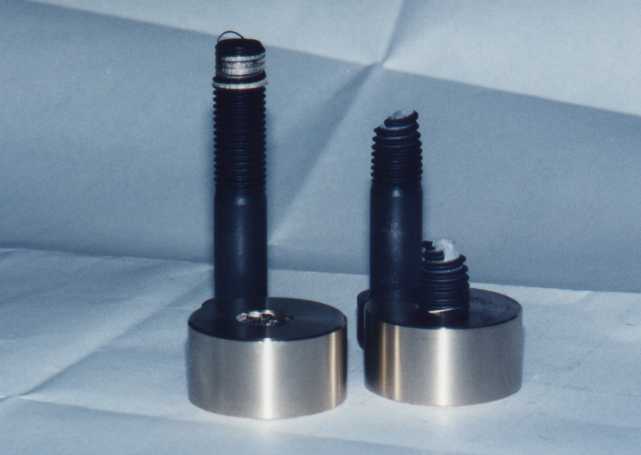
By looking at the stripped screw on the left of Figure 1 one can easily see that in the screwed-in area the screw as well as the nut have been stripped. in this particular case the calculated and measured strip off diameter are in accordance. In general, it was determined that the slight deviations do occur, as can be seen in the experiment log in [4], [5] and [6]
Fig 1: Stripped thread and broken screw.
The illustrated experiments were carried out using screws M 20x110 in 8.8 and nuts from PAN-Bronze 220. The following values were determined:
Left: Length of thread engagement m = 15 mm, Traction F = 224.2 kN strip off diameter. dt= 18,70 mm
Right: Length of thread engagement m = 17 mm, Traction F =224.2 kN with screw break.
Two criteria are necessary for the screw connection:
1. To find out whether the thread is stripped or the screw broken in an over-load screw connection, the tensile strength of the material value must be considered. The determined minimum length of thread engagement is then enlarged by about 5 %. By doing this it was proven that in the case of over-load the screws will break.
2. In the case of a general verification where a safety against yielding point is required, the values of the yielding points must be considered to verify the strain and determine the recommended length of thread engagement.
The calculative methods are the same in both cases.
2 Calculation of the screw
2.1 Symbols and Notations (Also
see SAE J 475 A, Table 7, Page 82, Print of October 18, 1999)
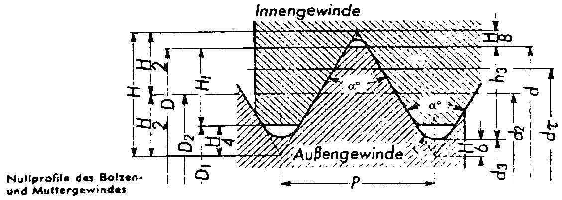
Fig. 2: Basic profile of the screw and the nut threads.
The following general symbols are used in Figure 2:
F General Forces
FV General Preload
FBr = RmB*As Screw break load
MA Torque of tightening screw
a B,M Material factors of screw or nut
b B,M Shearing tension factors
a ° Flank angle
RmB,M Tensile strength of the screw or nut material
RpB,M Yielding point of the screw or nut material
t mB,M = bB,M*RmB,M Shearing tension limit of the screw or nut
t pB,M = bB,M*RpB,M Screw or nuts shear tension limit at the yielding point
t B,M,vor Existing screw or nut shearing tension
d, d2 Major diameter. pitch diameter
dt , m Diameter of strip off cylinder, Length of thread engagement (LE)
As Stress cross section of the screw
At Total surface of strip off cylinder
At B,M Strip off surface of the screw or nut thread
P, H Pitch, height of fundament triangle.
In order to determine the acceptable shearing tension in few different b shear tension factor must be considered, depending on the material used. The current testing has revealed values as presented in Program SR 1 for the screws and the nuts material. in the tests in which the screws from the series production with a tolerance of 6g and nuts with a tolerance of 6H were created, the screw broke in parts of the thread (with the exception of the rolled screw made of stainless steel). All influences from the materials, the tolerance 6H/6g and the groove/notch influence (groove number a k and the base factor u ), just as the bending- and pushing tension, were found in the shearing tension factor b .
2.3 Determination of the length of thread engagement
During the currently mentioned tests it was also determined that a minute expansion of the nut material, expansion A < 4 % with a resemblance to if not almost equal-traction, did not strip the thread levels of the screws or nuts, rather the nut (as can be seen in figure 3) exploded in a bullet-panned shape. This was also proven in the below illustrated PAN-Bronze 16, as well in cast iron and in the cast aluminum.
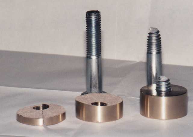
Fig. 3: Exploded bullet-panned shaped nut PAN 16 with screw M 20 x 110 from 5.6
Left: Length of thread engagement m = 17 mm, Traction
F
= 135, 6 kN, exploded nut
Right: Length of thread engagement m = 19 mm, Traction
F
= 135,8 kN with screw break.
Comment: It was determined that with certain material combinations the recommended length of thread engagement can be smaller than the minimum length of thread engagement. For this reason both cases should be calculated.
2.3.1 Minimum length of thread engagement for screw breakage
This is where the tensile strength of the material must be employed. under the assumption that the stripping tension factors are not the same, the following calculation process is realized:
Keeping the acceptable shear tension in mind, the strip off diameter must be determined. The acceptable shear tension for the screws and nuts are constructed so:
t mB = bB*RmB t mM = b M*RmM.
The opposite relation to acceptable shear tension result from the material factors of the screws and nuts through:
a B = tmM/(t mM+tmB) a M = 1-aB.
In the middle of the theoretical thread lies the pitch diameter d2
between the Thread tips. The measure-ment from the pitch diameter d2
to the tip of the thread is H/2. Half of the diameter is transformed
to the value
D d/2 = H/2-HB/2
although
HB = a B*P/tan
(a °/2)
when using different material values, such as breaking point e.g. yielding
points.
Upon including of the pitch diameter d2, the value 0.5 = tan (a °/2)*H/P and the factor a B have the strip off diameter
dt = d2 + (0.5-aB)*P/tan (a °/2).
As the pitch here is included so varying length of thread engagement for the standard and fine threads will be as a result.
The breaking load of the screws results to
FBr = RmB*As.
With this strength the strip off cylinders recommended shear surface
becomes
At = FBr*(1/tmM+1/t
mB)
Under the influence of the strip off diameter, the minimum length of
thread engagement becomes
mmin = At /(dt*p
).
At this length of thread engagement, "equilibrium" exist between the loaded thread levels and the stress cross section tension of the screws. in order to avoid stripping, the minimum length of thread engagement must be increased. An increase of about 5 % is recommended.
2.3.2 Recommended length of thread engagement under work loads
Under the mandatory securities for the yielding point, the securities cannot only be limited to the cross section tension of the screw, rather, it should of course be that these same securities are present in the thread levels, and in a sack or threads clearance hole. Since the acceptable tension acts proportionally during the securities. the recommended length of thread engagement with the tension at the yielding point and the minimum value of the yielding point can be calculated.
The tension at the yielding point amounts to
Fp = As*Rp
and the shear tension of the screw and nut
t pB = bB*RpB
t pM = b
M*RpM.
With these values the material factor for the screws and the nuts amounts
to
a B = tpM/(t
pM+tpB) a
M = 1-aB
and the strip off diameter
dt = d2+(0.5-aB)*P/tan
(a °/2).
The strip off surface of the strip off cylinder is then
At = Fp*(1/tpM+1/t
pB)
The strip off diameter dt amounts
the necessary length of thread engagement of
merf = At /(dt*p
).
The currently known shear tension factors are listed in the table of Program SR 1. If a material is used in which the shear tension factor bM is not yet known, the conservative bM = 0.5 should be used an with kneaded aluminum bM = 0.4, as long as the shear tension factor cannot be determined according to section 2.3.4.
2.3.3 Calculation of the threads shear tension
In order to determine the current shear tension of the screws operational
power and the current safety during an existing screw connection, the material
values of the material factors must be determined
a B = tpM/(t
pM+tpB) a
M = 1-aB
and thereby the strip off diameter
dt = d2 + (0.5-aB)*P/tan
(a /2°)
Hereby the shear surface of the strip off cylinder is calculated at
At = dt*p
*m.
These values are returned in relation to the material factors of the
screw and nut parts using
At B = At*a
B AtM = At
*aM
These values allow for the calculation of the individual shear tension
of the screw and nuts threads
t B,vor = F/AtB
t M,vor = F/AtM.
The securities of the screws and nuts can be calculated by
n B = tpB/t
B,vor nM = t
pM/tM,vor.
It should be n B = nM
> 1,5.
2.3.4 Determination of the shear tension factor b B,M
For factor calculation it is highly recommended that tests be conducted since form variation theory from von Mises is not always correct, as can be seen from the table in Program SR 1. Under the assumption that the nut material is unknown, the yielding points at the tension values from the test pieces must be determined. Using a screw thread whose material factor is known, a strain test for the determination of the tension and breaking point is conducted. in order to pre-evaluate the length of engagement, it is assumed for the nut material that it carries the factor bM » 0,58. The length of engagement can be calculated using the formulas in section 2.3.1. Either the thread will be stripped off or the screw will beak as a result of the test. In the case of a stripped off thread, the diameter of the stripping can be measured on the tapped hole as well as on the screw. The approximate shear tension factor of the nut material can be calculated through the values of the tension, the mean value of the measured strip off diameter an the loaded length of thread engagement both determined through the testing.
Using the resulting measurements, the entire strip off cylinder can
be calculated through
At = m*dt*p
The "mathematical shear tension" for the screw can be calculated through
the shearing strength determined during the actual shearing:
t mB = bB*F/As,
whereas the known bB are listed in
Program SR 1.
Using these values the "mathematical shear value" of the nut can now
be calculated:
t mM = (At/F-1/t
mB)-1
Thus the shear tension factor becomes
b M = tmM/RmM
.
Using these values, a control calculation according to the section
2.3.1
formulas must be conducted using the breaking point of the screws, in order
to be able to calculate the breaking point at certain length of thread
engagement in future test. As the test results in [5]
show, two tests may suffice given the right conditions.
It must be emphasized that the shear tension factor is too inexact when the distance of the breaking point is too far from the strip off point. For this reason the length of thread engagement and the determined points should be close to each other during two tests and at the lager point, the screw break should be followed.
It must further mentioned, that when using stainless steel screws with rolled threads, the screw break is not seen in the stress cross section of the screw, but in the shaft portion as can be seen in Figure 4. This is the result of a material strengthening from the thread rolling.
Despite the break in the shaft, the stress cross section tension of
the thread must be considered when calculating the length of thread engagement,
so with
F = Rm*As.
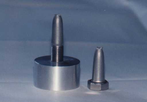
Fig. 4: Stainless Steel Screw A2-70, M 16 with Aluminum nut from 3.0615.71 (F 28)
Length of thread engagement: m = 21 mm, Extension: 25 mm, Breaking load: F = 128 kN
If the screws shear tension factor should be determined instead of the nut material, it is logical to proceed according to those values.
2.4 Consideration of the Tolerance
The threads are not always produced in the usual tolerance of 6H/6g,
but also with larger variations. In this case ist must be recognized the
length of thread engagement will be that much longer according to the result
of the tolerance measurements. Experience shows these measurements not
to be very large, so that under an approximate 5 % enlargement of a technical
screw length, such a deviation can be compensated.
Deviations from the usual tolerance has only a very slight effect on the measurement of the strip off diameter. Under the assumption that the power attack occurs in the strip off diameter, it can be assumed that the resulting strains of bending in the thread do not behave any differently than when the usual tolerance is present. In Program SR 1 the influences of the tolerance will be discussed.
According to mathematical verification, the corresponding tolerance table adhere to the norms and they are presented as examples of the metric ISO standard thread in the DIN 13, part 20 and for the fine thread in DIN 13, part 21.
2.5 Acceptable Surface Pressure Underneath the Head of the Screw
Within the realm of a dissertation, experiments were conducted at the Technical University in Darmstadt (Germany) in order to determine the acceptable surface pressure in the head of a screw and underneath the nut. The results are presented in [7].
According to the experiments, the acceptable surface pressure was dependent upon Brinell hardness of the material. Independent of the alloy, also with gray cast iron, stainless steels, the current minimum Brinell hardness was converted to the "mathematical tensile strength" through the table in DIN 50150. The determined value pG is found in [7] underneath the value pG,0,025 mm, where a lasting deformation of 25 µm begins. Since under the iron steels there is a strong reference of HB to Rm , the formula pG = Rm can therefore be set for these steels. The determined acceptable surface pressure pG , which are an a prominent basis, are also presented in the Program SR 1 material tables.
The surface pressure is calculated an the basis of Junker with
the formula
Fmax = Maximal screw strength
(FM+F *FA,,
whereas F = FSA/FA
according to VDI 2230)
dw = Loading external diameter of the screw head
or nut
da = Loading internal diameter of the drilling, eventually
exclusively indentation.
The occurring surface pressures along with the loaded surface amounts
to
Ap = (dw²-da)*p
/4
pvorh = Fmax/Ap£
pG.
If the surface pressure is too great, the loaded surface can be enlarges
by means of a washer with the appropriate breaking point. The external
diameter is then enlarged to
dw = dw+2s
where s is the thickness of the washer. If this measurement turns
out to be larger than the external diameter of the washer, the smaller
measurement should be considered.
Among the various types of threads only the formula of the strip off diameter changes, since the half-flank angel is used here. Further calculative steps. As already listed, do not change.
With the trapezoid, round and sawing threads. The deviating and loaded surface levels will also be pointed out.
2.6.1 Metrical Threads according to DIN 3 and
13
When using metrical threads, the flank angle is a
° = 60 °. Since in this case the fundament triangle is H
= 0.86603*P, the numerical value becomes 0.86603*tan 30° = 0.5.
Therefore the formula for the strip off diameter is
dt = d2 + (0.5-aB)*P/tan
30°.
Whitworth-thread, as well as standard, fine and pipe threads have
a flank angle of a ° = 55°, as long
as they are not converted to a flank angle of a
° = 60°. Since in this case the fundament triangle is
H = 0.960491*P
the numerical number of interest becomes 0.960491*tan 27.5° = 0.5.
Taking the pitch diameter d2 into consideration, the
formula for the strip off diameter is
dt = d2+(0.5-aB)*P/tan
27.5°.
2.6.3 Thread of a Steel Pipe Shell
The thread of a shell thread has a flank angle of a
° = 80° with a fundament triangle of
H = 0.595875*P.
The numerical value then becomes 0.595875*tan 40° = 0.5. In consideration
of the pitch diameter the formula is for the strip off diameter
dt = d2+(0.5-aB)*P/tan
40°.
2.6.4 Trapezoid Thread according to DIN 103
Trapezoid thread are generally used in spindles. If the area of the
screw extension of group N and L are suggested in DIN 103, part 3, Table
3 and in Table 9 the corresponding tolerance fields are named, then the
majority of the acceptable surface pressures at which a gliding movement
is still possible, will tentatively be standard. In spite of this, it must
be made sure during the material pairing that the strip off diameter lies
within the thread' flank.
With the flank angle of a ° = 30°
for the trapezoid thread and a fundament triangle of
H = 1.866*P
the numerical value becomes 1.866*tan 15° = 0.5. Thus the formula
for the strip off diameter in consideration of the pitch diameter is
dt = d2+(0.5-aB)*P/tan
15°.
From DIN 103, part 1 (see Fig. 2 and Fig. 3) is follows that the thread
depth of the base profile
H1 = 0.5P . In reference to the loaded height
the maximum strip off diameter is
dt = d2+H1
= d2+0,5P
Since the value is (0.5-a B)*P/tan
15° = 0,5P the maximum material factor becomes
a B = 0.5-0.5*tan 15° = 0.366
for the largest strip off diameter. For the smallest strip off diameter
is the material factor
a B = 1-0.366 = 0.634
With these values the strip off diameter would be at the thread tip of the screw and nut.
To make sure that the strip off diameter does not lies an the tip of
the thread, the following condition should be fulfilled
d > dt > D1
This condition has been met when the material factor
a B = 0.375 up to 0.625
respectively, when the relation of the shear tension is
t pM/tpB
= 3/5 up to 5/3
That would correspond to a loaded flank height of 0.467P.
Fig. 5: Profile of Screw and Nut Thread
In addition of the symbols in Figure 2, the following symbols should be observed
D1 [mm] Minor diameter of the nut thread
P [mm] Pitch of the single thread and separation of the multiple thread
Fs [N] Operation power of the spindle
AK [mm²] Stress cross section of the spindle
Apw [mm²] Surface for surface pressure per turn
Ap,erf [mm²] Recommended surface for compression
werf [--] Recommended coilage during compression
mw [--] Recommended nut height from the compression
s [mm] Slacking of the flank
The spindle is the starting point for calculating the material pairing.
With the spindle data the strength at the yielding point is first determined
FpB = Fs*n
where Fs is the operating power and n
the necessary security.
Once the spindle data is known, the following stress cross section can
be found
AK = d3²*p
/4
and the recommended yielding point of the screw material becomes
RpB = FpB/AK.
so that the material for the spindle can thereby be determined.
If the material is indeed given, the stress cross section can be determined
to
AK = FpB/ RpB,
so the spindle data can thereby determined.
For the determination of the nut material, the relation of the shear
tension should be observed. From this the yielding point of the nut material
converts to
RpM = RpB*bB*3/(5*b
M) bis RpB*bB*5/(3*b
M).
Since with a few of the bronze materials the acceptable surface pressure
during gliding movements is provided, the minimum number of coils from
the operational power can be calculated. The recommen-ded surface carries
Ap,erf = Fs/pzul.
With the surface per turn
Apw = d2*p
*P/2
the number of recommended turns becomes
werf = Ap,erf/Apw.
Thus, the recommended nut height from the surface pressure becomes
mw = werf*P.
The calculation of the recommended nut height in consideration of the securities can be done as shown in section 2.3.3. The now larger nut height is then standard for the completion of the construction.
As can be seen in Figure 6, the trapezoid turns with flank slack are
produced. Here as well, the strip off diameter is
dt = d2+(0.5-aB)*P/tan
15°
To determine the recommended length of thread engagement, the existing flank slack is to considered, although the standard limit for the nut threads can be deduced from DIN 103, pages 5 and 6, and for the screw thread pages 7 and 8.
Fig. 6: Profile with Flank Slack
The recommended length of thread engagement expands in relation to the degree that comes from the number of pitches and doubled tolerance standards s/2.
2.6.5 Round Threads according to DIN 15403 for Crane Hooks
Caution: The descriptions of round threads deviate from the usual formulas! The formulas refer to the specifications in Figure7.
As with the previous threads, the round threads with a flank angle of
a
° = 30° and a height of the fundamental triangle of
t = 1.866*h
carry the numerical value 1.866*tan 15° = 0.5.
In the case of the round threads, the flank angle with the short-carrying
flank carries as with most threads a value of a
° = 30°. Therefore the formula for the strip off diameter is
dt = d2+(0.5-aB)*P/tan
15°
As was already shown in the case of the trapezoid thread, the strip
off diameter cannot lie outside of the loaded flank surface. The result
is the conversion from t2 = (0.5-aB)*h/tan
15° = 0.27234*h for the material factors for the major strip
off diameter to
a B = 0.5-0.27234*tan 15°
= 0.427
and for the minor strip off diameter to
a B = 1-0.427 = 0.573.
Fig. 7: Round thread according to DIN 15403
The following technical data must still be observed:
Pitch h » d/9
Height of Fundamental Triangle t = 1.866*h
Depth of thread t1 =0.55*h
Depth of the loaded flank t2 = 0.27234*h
freedom of the thread head/rounded a = 0.05*h
Radius at the base of the thread r1 = 0.22104*h
Radius at the tip of the thread r2 = 0.15359*h
Since in this case the loading surface does not end at the threads tip, it is not recommended that the loading surface be reduced.
Further length of thread engagement, shear tension and security calculations follow as presented in section 2.3.3.
2.6.6 Saw Threads according to DIN 513, part 1 to 3 (April 1985)
The saw thread is mostly used as a movement screw just like the trapezoid thread. In contrast to the trapezoid thread, it has the advantage that the radial strength from the surface contraction at a flank angle of 3° becomes much smaller then the trapezoid thread with an angle of 15° for the loaded flank.
For standard technical reasons, the non-loaded flank angle of 30°, as well as the loaded flank angle of 3°, must be considered for the height of the fundamental triangle.
Fig. 8: Base profile of the saw threads.
Fig. 9: Profile of screw and nut threads with slack on the non-loaded flank in the minor diameter and without slack between the loaded flanks of the major diameter (Standard size).
The order of the major diameter and the pitch can be found in the table in DIN 513, part 2, section 4.
Fig. 10: Determination of the Substitute Angle.
With consideration of the sine theorem, the height of the profile triangle
calculates to
H = ctg 30° *sin 30°/sin 147°*cos 3° = 1,5879*P.
in this case, a mathematical angle substitute was necessary in order
to calculate the strip off diameter. The substitute angle is
ctg a substitute = ctg 30°
*sin 30°/sin 147°*cos 3° = 1.5879,
consequently, the mathematical angle substitute has a value of
a °substitute = 32.201°
To calculate the strip off diameter, as carried out in section 2.3.3,
the materiel factor a B is required
which can be calculated at
a B = tM/(t
M+tB).
With consideration of the pitch diameter and the mathematical substitute
angle, the strip off diameter is calculated to
dt = d2+2(0.5-aB)*P/tan
32.2°.
From DIN 513, part 1 (see Fig. 2) it follows that the thread depth of
the base profile has a value of
H1 = 0.75P. When regarding the loaded height,
the maximum strip off diameter results so:
dt = d2+H1
= d2+0.75P.
Since the value is 2*(0.5-a B)*P/tan
32.2° = 0.75P, than (0.5-a B)
= 0.75*tan 32.2/2 = 0.2362 from which the maximum material factor can be
determined to be
a B = 05-0.2362 = 0.2638 aM
= 1-a B
for the largest strip off diameter. For the smallest strip off diameter
the value is
a B = 1-0.2638 = 0.7362.
With these values, the strip off diameter would lie between the tips
of the screw and the nut thread.
To make sure that the strip off diameter does not lie on the tip of
the thread levels, the following condition must be fulfilled:
d > dt > D1.
This condition has been fulfilled when the material factor is
a B = 0,3 up to 07.
The recommended shear surface of the shearing cylinder together with
traction F, as calculated from the stress cross section with the
breaking point specifically, the minimum yielding point is
At = F*(1/tM
+ t B).
With this value the length of thread engagement becomes
m = At /(dt*p
).
According to DIN 513, Fig. 2 (see also Fig. 9) an axial slack of
a = 0,1*Ö P
is found an the non-loaded flank.
To offset the empty place, the following number of thread levels is
recommended
Z = m/P.
This results in the compensation length
ma = Z*a = Z*0,1*ÖP
Thereby the effective length of thread engagement becomes
meff = m+ma.
The calculation of the shear tension which appear in the thread levels and are present in the securities are calculated just as in section 2.2.3.
To calculate the trapezoid and saw thread spindles, a few of the PAN-Metal
nut materials are introduced in the following table
.
Table 1: PAN-Metals
| PAN-
Metals |
Production | R0,2
[N/mm²] |
Rm
[N/mm²] |
Hardness
HB 10 |
s d0,2
=
pG
[N/mm²] |
pmax
[N/mm²] |
b M | E-Modula
[N/mm²] |
a T |
| Bz. 10 | G | 150 | 280 | 75 | 160 | 40 | 110000 | 0,0000175 | |
| GZ, GC | 170 | 320 | 90 | 160 | 40 | 110000 | 0,0000175 | ||
| Bz. 12 | G | 180 | 300 | 95 | 210 | 50 | 0,64 | 100000 | 0,0000180 |
| GZ, GC | 200 | 350 | 110 | 210 | 60 | 0,64 | 100000 | 0,0000180 | |
| Bz. 14 | G | 170 | 250 | 115 | 180 | 60 | 0,68 | 95000 | 0,0000185 |
| GZ, GC | 200 | 320 | 125 | 180 | 65 | 0,68 | 95000 | 0,0000185 | |
| SoBz 16 | G | 180 | 250 | 130 | 160 | 70 | 0,85 | 80000 | 0,0000185 |
| GZ, GC | 220 | 300 | 150 | 160 | 80 | 0,85 | 80000 | 0,0000185 | |
| AlMBz. 220 | G | 330 | 650 | 170 | 290 | 120 | 0,32 | 125000 | 0,0000170 |
| GZ, GC | 380 | 750 | 180 | 290 | 150 | 0,32 | 125000 | 0,0000170 |
Comment: G = Shaped casting, GZ = Centrifugal casting, GC = Strand casting, GK = Mould casting,
pmax = Max. Surface pressure at which gliding is still possible.
PAN-Metallgesellschaft Baumgärtner GmbH & Co.KG,
Am Oberen Luisenpark 3, D 68165 Mannheim
[1] Stückle, R. "Berechnung der Schrauben
(nach Bach)",Uhlands Ingenieur-Kalender 1939,
65. Jahrgang, Teil II, Seite 104 und 105, Kröner Verlag Stuttgart,
1938
[2] Alexander, E.A. "Analysis and design of threaded assemblies". Int. Automotive Engng.
Congress and Exposition, Detroit. 1977 Rep.-Nr.770420.
[3] Richtlinie VDI 2230, Bl. 1:Systematische Berechnung hochbeanspruchter
Schraubverbindungen (Juli 1986, korregierter Nachdruck 1990)
[4] Dose, G.F.; Pittner, K.-J. "Neuartige Berechnung von Schrauben unter Berücksichtigung der Werkstoffkennwerte", Konstruktion 48 (1996), Heft 6, Seite 183 bis 188,
Springer Verlag, Berlin
[5] Dose, G.F. "Ermittlung der Scherspannungsfaktoren für die neuartige Schraubenberechnung", Konstruktion 49 (1997) Heft ½, Seite 28 bis 32, Springer-VDI-Verlag, Düsseldorf.
[6] Dose, G.F. "Anwendung eines Schraubenberechnungs-Verfahrens auf verschiedene Gewindearten", Konstruktion 50 (1998) Heft 7/8 , Seite 45 bis 49, Springer-VDI-Verlag, Düsseldorf.
[7] Hasselmann, Uwe, "Grenzflächenpressung verspannter Teile", Vortrag zur 5. Informations- und Diskussionsveranstaltung SCHRAUBENVERBINDUNGEN - Neue Ergebnisse aus
Forschung und Praxis, TU Darmstadt.